Tag Archives: insert injection molding process

How to Design Injection Molded Parts: Complete Expert Guide with Case Studies

For a perfect part for injection molding,

First, we need to understand the basics of injection molding. As we know it’s a manufacturing process where plastic is melted and injected into a mold to create parts. But to write a guide, we should delve deeper into how the process works, the materials involved, and the common applications. Maybe we should start by explaining the injection molding process step by step.

Next, the design considerations. This seems crucial because designing for injection molding requires specific knowledge to ensure parts can be manufactured efficiently. we should think about factors like part geometry, material selection, tolerances, and draft angles. Wall thickness is another important aspect—too thick and it might cause sink marks or warping, too thin and it might not be strong enough.

Then, we need to cover the design for manufacturability (DFM). This includes aspects like minimizing undercuts, avoiding complex geometries that could complicate the mold design, and ensuring proper ejection from the mold. Maybe we should also talk about the importance of draft angles and how they facilitate part ejection without damaging the mold or the part.

Material selection is another big topic. Different plastics have different properties—some are more flexible, others are rigid, some can withstand high temperatures. we should explain how the choice of material affects the design, such as shrinkage rates and thermal expansion, which can impact the final dimensions of the part.

Next point to address is the tooling and mold design. This includes the layout of the mold, runner systems, gates, and ejector pins. It’s important to explain how the placement of these elements can influence the quality and consistency of the molded parts. We will be discussing common mold types, like single-cavity vs. multi-cavity molds, and the trade-offs between them.

Surface finishing and textures are another aspect to cover. Different finishes can affect the aesthetics and functionality of the part. Next, we will explain the various options available and how they are applied during the molding process.

Considering assembly and post-molding operations is also essential. If the part is going to be assembled with other components, the design should accommodate that, perhaps with features like snap fits or bosses for screws. Additionally, post-molding steps like painting or adding labels should be considered in the design phase.

Testing and validation are critical before moving to mass production. I should talk about the different types of testing, such as mechanical testing to check strength and durability, and thermal testing to see how the part behaves under different temperatures. Prototyping with methods like 3D printing can help catch design flaws early on.

Sustainability is becoming increasingly important, so we should include a section on designing for recyclability and reducing material waste. Maybe discuss how using bioplastics or optimizing part weight can make the product more environmentally friendly.

Cost considerations are also vital. We need to explain how design choices can impact production costs, such as complex geometries leading to more expensive molds. Offering tips on how to balance performance with cost-effectiveness would be helpful.

Including case studies could provide real-world examples of successful injection-molded parts and the challenges faced during their design. This would make the guide more practical and relatable.

Finally, we should wrap it up with best practices and future trends in injection molding, like advancements in materials, automation, and digital manufacturing. This would give readers a sense of where the industry is heading and how they can stay ahead.

Injection molding is one of the most widely used manufacturing processes for producing plastic parts. It offers high precision, scalability, and cost-effectiveness, making it a preferred method for industries ranging from consumer goods to automotive. However, designing parts for injection molding requires a deep understanding of the process, materials, and design principles. This guide provides expert insights into designing parts for injection molding, ensuring that your designs are manufacturable, efficient, and meet the required performance standards.

Table of Contents

1. [Introduction to Injection Molding](#introduction-to-injection-molding)
2. [Design Considerations for Injection Molding](#design-considerations-for-injection-molding)
3. [Material Selection for Injection Molding](#material-selection-for-injection-molding)
4. [Design for Manufacturability (DFM)](#design-for-manufacturability-dfm)
5. [Tooling and Mold Design](#tooling-and-mold-design)
6. [Surface Finishing and Textures](#surface-finishing-and-textures)
7. [Assembly and Post-Molding Operations](#assembly-and-post-molding-operations)
8. [Testing and Validation](#testing-and-validation)
9. [Sustainability in Injection Molding](#sustainability-in-injection-molding)
10. [Cost Considerations and Optimization](#cost-considerations-and-optimization)
11. [Case Studies and Examples](#case-studies-and-examples)
12. [Best Practices and Future Trends](#best-practices-and-future-trends)

Introduction to Injection Molding
Injection molding is a manufacturing process where molten plastic is injected into a mold cavity. Once the plastic cools and solidifies, the mold opens, and the part is ejected. This process is highly versatile and can produce parts with complex geometries, tight tolerances, and high volumes.

Key Components of Injection Molding
1. Plastic Material: The raw material used, typically thermoplastic or thermosetting polymers.
2. Mold: A metal cavity that shapes the molten plastic into the desired form.
3. Injection Unit: Responsible for melting the plastic and injecting it into the mold.
4. Ejection System: Mechanism that removes the part from the mold after cooling.

Advantages of Injection Molding
– High Volume Production: Suitable for producing large quantities of parts.
– Complex Geometries: Capable of creating intricate shapes and features.
– Low Labor Costs: Automated process reduces the need for manual intervention.
– Material Efficiency: Minimal waste compared to other manufacturing methods.

Common Applications
– Consumer goods (e.g., household items, electronics)
– Automotive components
– Medical devices
– Packaging

Design Considerations for Injection Molding

Designing parts for injection molding requires careful consideration of several factors to ensure manufacturability, functionality, and cost-effectiveness.

Part Geometry
– Wall Thickness: In injection molding, wall thickness plays a crucial role in ensuring part quality, strength, and manufacturability. Ideally, walls should be uniform to promote consistent cooling and prevent defects like warping, sink marks, or internal stresses. Recommended thickness varies by material—ABS (1.2–3.5 mm), Polypropylene (0.8–3.0 mm), and Polycarbonate (1.0–4.0 mm). Avoid abrupt changes in thickness; instead, use gradual transitions or tapers to maintain flow consistency. Overly thick sections can lead to long cooling times and defects, while very thin walls may result in incomplete filling. Always balance strength, material flow, and mold ability when deciding wall thickness for optimal injection-molded part performance.

– Draft Angles: In injection molding, a draft angle is the slight taper applied to vertical surfaces of a part to facilitate easy ejection from the mold. Without adequate draft, parts can stick, causing damage or requiring excessive ejection force. A typical draft angle ranges from 1° to 2° per side, but more may be needed for textured or deep parts. Proper draft improves mold longevity and ensures smooth part release, reducing defects and production delays. All faces perpendicular to the mold opening direction should have draft applied. Designing with draft in mind is essential for moldability, efficiency, and consistent part quality.


– Radius and Fillets: In injection molding, radii and fillets are rounded transitions between surfaces that reduce stress concentrations, improve material flow, and enhance part strength. Sharp corners, especially internal ones, can cause weak points, warping, or incomplete filling. Adding fillets (internal curves) and radii (external curves) helps maintain uniform wall thickness and reduces wear on the mold. A good rule is to use an internal radius of at least 0.5× the wall thickness and match external radii accordingly. These smooth transitions also aid in ejection and overall part aesthetics. Proper use of fillets and radii is essential for durable, high-quality molded parts.


2. Material Selection

– Thermoplastics: Commonly used due to their re-meltable nature (e.g., PP, ABS, PC).
– Thermosets: Used for high-temperature applications but are not reusable once set.
– Additives: Include fillers, colorants, or reinforcements based on the desired properties.

3. Tolerances

– Dimensional Tolerance: Typically ±0.1mm to ±0.5mm, depending on the material and part size.
– Surface Finish: Specify surface roughness (e.g., Ra 1.6 to Ra 12.5) based on the application.


4. Ejection and Mold Release

– Ejector Pins: Ejector pins are critical components in injection molding that push the finished part out of the mold once it has cooled and solidified. Located on the mold’s core side, they apply a controlled force to release the part without causing damage or deformation. Ejector pins are typically round and leave small, often visible marks on non-cosmetic surfaces. Proper pin placement is crucial to avoid warping or sticking, especially on large or thin-walled parts. Designers should provide flat, reinforced areas—called ejector pads—for pin contact. Effective ejection ensures consistent cycle times, part quality, and mold longevity in high-volume manufacturing.
-Mold Release: Design features to minimize the need for mold release agents, such as textured surfaces or draft angles.


5. Ribs and Bosses

– Ribs: Ribs in injection molding are thin, protruding features used to reinforce plastic parts without adding excessive material or increasing wall thickness. They enhance structural rigidity, prevent bending, and support other features like bosses or mounting points. To avoid sink marks and warping, ribs should be designed with proper proportions: typically 50–70% of the adjacent wall thickness and no taller than three times that thickness. Draft angles of 0.5–1° and rounded bases help ensure smooth ejection and reduce stress concentrations. Well-designed ribs improve mechanical performance while maintaining moldability, ensuring strong, lightweight, and visually acceptable injection-molded components.
– Bosses: Bosses in injection molding are raised cylindrical features typically used for assembly purposes, such as accommodating screws, inserts, or aligning parts. They should be designed with wall thickness no more than 60% of the adjoining wall to avoid sink marks and warping. Adding fillets at the base and reinforcing them with ribs or gussets enhances strength. Proper draft angles (typically 0.5–1°) help with ejection. Well-designed bosses improve part functionality, structural support, and manufacturability.


6. Holes and Threads

– Hole Diameter: In injection molding, hole diameter must be carefully designed to ensure moldability and part strength. Small holes can be difficult to mold accurately, while large holes may weaken the structure. A minimum diameter of 1 mm is recommended, depending on material and wall thickness. Holes should be placed with enough spacing from edges and other features to prevent stress concentration. For deep holes, core pins are used, and slight draft may be added to aid ejection and reduce wear.
– Threads: In injection molding, thread diameter must be designed to ensure accurate molding and part strength. External threads are easier to mold than internal ones and should include a draft angle of 1–2° for smooth ejection. For internal threads, collapsible cores or unscrewing mechanisms may be required, increasing mold complexity. Threads should be coarse rather than fine to ensure proper filling and durability. The minimum recommended thread diameter is typically 5 mm, with sufficient clearance to avoid weak walls or distortion.

7. Snap Fits and Assembly Features

– Snap Fits: Design cantilever beams with adequate deflection (0.5mm to 2mm) and return angle (30° to 45°).
– Assembly Features: Incorporate alignment features (e.g., guide pins, keyways) for ease of assembly.


8. Mold Flow and Fill Analysis

– Flow Length-to-Thinness Ratio: Optimize the flow path to ensure even filling and minimize material pressure.
– Weld Lines: Avoid placing critical features where weld lines may form, as they can weaken the part.

9. Cooling and Shrinkage

– Cooling Time: Ensure sufficient cooling time to prevent warping and dimensional inaccuracies.
– Shrinkage: Account for material shrinkage (typically 0.1% to 2%) in your design.

10. Aesthetics and Branding
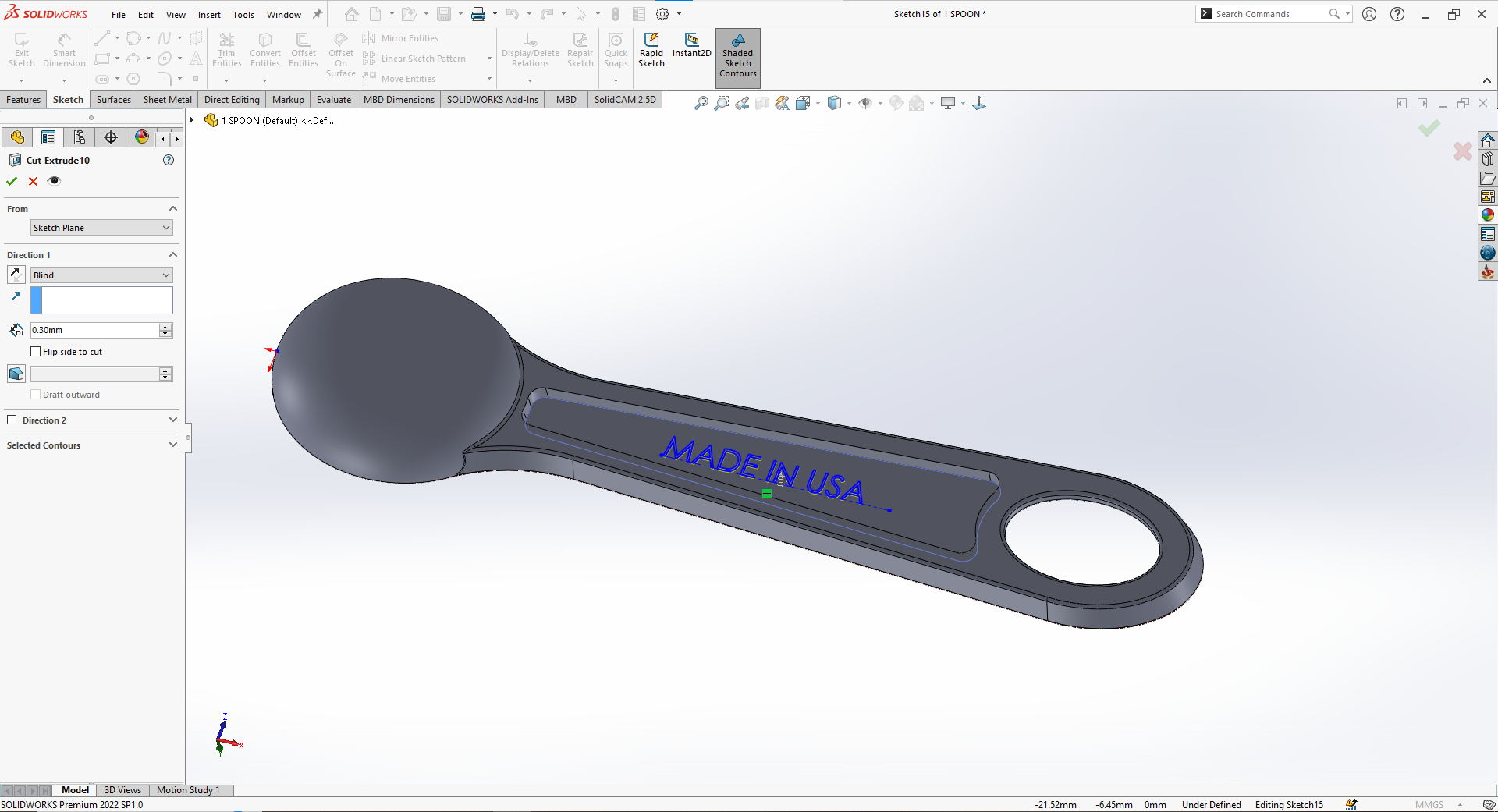
– Logos and Markings: In injection molding, logo engraving should be designed with clear, moldable dimensions to ensure readability and ease of manufacturing. The minimum line width (diameter) for engraved features is typically 0.25 mm, depending on the material and mold precision. Engravings should not be too deep—usually 0.1 to 0.3 mm—to avoid sink marks and ensure smooth ejection. Placement on flat, non-critical surfaces is ideal. Adequate draft angles (at least 1°) help prevent damage during demolding and improve logo clarity.


Material Selection for Injection Molding
The choice of material is critical for the performance, cost, and manufacturability of your part.

Common Materials
1. Polypropylene (PP): Lightweight, flexible, and chemical-resistant.
2. Acrylonitrile Butadiene Styrene (ABS): Impact-resistant and suitable for high-temperature applications.
3. Polycarbonate (PC): Transparent, impact-resistant, and suitable for optical applications.
4. Polyethylene (PE): Low-cost, flexible, and chemical-resistant.
5. Polyester (PET): High-strength, rigid, and suitable for packaging.

Material Properties to Consider
– Mechanical Properties: Tensile strength, impact resistance, and flexural modulus.
– Thermal Properties: Heat deflection temperature (HDT) and thermal conductivity.
– Chemical Resistance: Compatibility with chemicals and cleaning agents.
– Optical Properties: Transparency, gloss, and UV resistance.

Additives and Fillers
– Reinforcements: Glass fibers for increased strength and stiffness.
– Fillers: Minerals like calcium carbonate to reduce material costs.
– Colorants: Pigments or masterbatches for custom colors.
– UV Stabilizers: To prevent degradation from UV exposure.

Sustainability Considerations
– Recyclability: Choose materials that are recyclable or biodegradable.
– Bioplastics: Consider PLA (Polylactic Acid) or PHA (Polyhydroxyalkanoates) for eco-friendly applications.
– Material Efficiency: Optimize part weight and thickness to minimize material usage.

Design for Manufacturability (DFM)
Design for Manufacturability (DFM) is a critical aspect of injection molding that ensures your part can be produced efficiently and cost-effectively.

Key DFM Principles
1. Simplify the Design: Avoid unnecessary complexity that could increase tooling costs or lead to manufacturing defects.
2. Minimize Undercuts: Undercuts require side actions in the mold, which increase tooling complexity and cost.
3. Avoid Thin Walls: Ensure wall thickness is consistent and within recommended limits to prevent warping and sink marks.
4. Use Standard Features: Standardize features like bosses, ribs, and snaps to reduce design variability.

Moldability Analysis
– Flow Analysis: Use simulation tools to analyze how molten plastic flows into the mold cavity.
– Pressure Drop: Ensure that the pressure drop is within acceptable limits to avoid material degradation.
– Cooling Analysis: Optimize cooling channels to ensure uniform cooling and minimize warping.

Design for Assembly (DFA)
– Snap Fits: Use snap fits to eliminate the need for fasteners.
– Alignment Features: Incorporate guide pins, keyways, or chamfers to facilitate easy assembly.
– Modular Design: Design parts that can be easily assembled into a complete product.

Cost Reduction Strategies
– Reduce Material Usage: Optimize part weight and thickness to minimize material costs.
– Simplify Tooling: Avoid complex mold features that increase tooling costs.
– Increase Production Volume: Take advantage of economies of scale by producing larger batches.

Tooling and Mold Design
The mold is a critical component of the injection molding process, and its design directly impacts the quality, cost, and lead time of your part.

Key Components of a Mold
1. Cavity: The part of the mold that shapes the plastic into the desired form.
2. Core: The part of the mold that creates holes or recesses in the part.
3. Runner System: Channels that direct molten plastic from the injection unit to the mold cavity.
4. Gates: Points where molten plastic enters the mold cavity.
5. Ejector Pins: Mechanisms that push the part out of the mold after cooling.

Mold Types
1. Single-Cavity Mold: Produces one part per cycle. Ideal for low-volume production.
2. Multi-Cavity Mold: Produces multiple parts per cycle. Ideal for high-volume production.
3. Family Mold: Produces multiple parts of similar size or shape. Reduces tooling costs.
4. Hot Runner Mold: Uses insulated runners to keep the plastic molten between shots. Reduces material waste.

Mold Materials
1. Steel: Most common mold material due to its durability and cost-effectiveness.
2. Aluminum: Used for prototype molds or low-volume production due to its faster machining time.
3. Beryllium Copper: Used for high-wear areas due to its high thermal conductivity.

Mold Surface Finish
– Polishing: Improves part quality and reduces mold wear.
– Texturing: Creates surface textures for aesthetic or functional purposes.
– Coating: Applies wear-resistant or corrosion-resistant coatings to critical areas.

Mold Maintenance
– Cleaning: Regularly clean the mold to prevent contamination and material buildup.
– Lubrication: Lubricate moving parts to reduce wear and tear.
– Inspection: Inspect the mold for damage or wear and perform repairs as needed.

Surface Finishing and Textures
Surface finishing and textures play a crucial role in the aesthetics and functionality of injection-molded parts.

Common Surface Finishes
1. Polished Finish: Achieved by polishing the mold cavity to a high gloss. Ideal for optical applications.
2. Textured Finish: Creates a specific surface texture for grip, aesthetics, or functionality.
3. Matte Finish: Provides a dull, non-reflective surface. Ideal for hiding mold marks or imperfections.
4. Etched Finish: Creates a fine, detailed texture using chemical etching.

Texture Patterns
1. Fine Texture: Provides a smooth, low-gloss surface.
2. Medium Texture: Offers a balanced combination of aesthetics and functionality.
3. Coarse Texture: Ideal for applications requiring high grip or durability.

Functional Textures
– Grip Textures: Used on handles, grips, and other areas requiring traction.
– Ventilation Textures: Create airflow or drainage in applications like filters or vents.
– Aesthetic Textures: Enhance the visual appeal of the part.

Application Methods
1. Mold Texturing: Textures are incorporated directly into the mold cavity.
2. Post-Molding Texturing: Textures are applied after molding using processes like laser etching or pad printing.
3. Insert Molding: Textures are molded into inserts that are then assembled into the final part.

Assembly and Post-Molding Operations
Many injection-molded parts require additional assembly or post-molding operations to meet their functional requirements.

Assembly Methods
1. Snap Fits: Use cantilever beams or other snap-fit features to eliminate the need for fasteners.
2. Ultrasonic Welding: Join parts using high-frequency vibrations to create a strong bond.
3. Adhesive Bonding: Use adhesives to join parts, especially when different materials are involved.
4. Screw or Rivet Assembly: Use mechanical fasteners for applications requiring high strength or adjustability.

Post-Molding Operations
1. Printing: Apply labels, logos, or other graphics using screen printing, pad printing, or laser marking.
2. Painting: Apply paint for aesthetic or functional purposes, such as color matching or UV resistance.
3. Plating: Apply metal coatings for conductivity, corrosion resistance, or aesthetics.
4. Machining: Perform secondary machining operations like drilling, tapping, or grinding for precision features.

Automation in Assembly
– Robotic Assembly: Use robots to automate repetitive tasks like screw driving or welding.
– Vision Systems: Use vision systems to inspect and guide assembly operations.
– Conveyor Systems: Use conveyor systems to move parts through the assembly line efficiently.

Design for Assembly (DFA)
– Simplify the Design: Minimize the number of parts and fasteners to reduce assembly time and cost.
– Modular Design: Design parts that can be easily assembled into a complete product.
– Alignment Features: Incorporate guide pins, keyways, or chamfers to facilitate easy alignment during assembly.

Testing and Validation
Before moving to mass production, it’s essential to test and validate your design to ensure it meets the required performance, safety, and quality standards.

Types of Testing
1. Mechanical Testing: Evaluate the part’s strength, stiffness, and impact resistance.
2. Thermal Testing: Test the part’s performance under extreme temperatures.
3. Chemical Resistance Testing: Assess the part’s resistance to chemicals and cleaning agents.
4. Optical Testing: Evaluate the part’s clarity, gloss, and UV resistance.
5. Functional Testing: Test the part’s functionality in its intended application.

Prototyping and Iteration
– Rapid Prototyping: Use 3D printing or CNC machining to create prototypes for testing.
– Design Iteratio: Refine the design based on test results and feedback.
– Design Freeze: Finalize the design once all issues have been resolved.

Quality Control
– Inspection: Regularly inspect parts for defects or variations.
– Dimensional Measurement: Measure critical dimensions to ensure compliance with specifications.
– Statistical Process Control (SPC): Monitor the production process to maintain consistent quality.

Sustainability in Injection Molding
As environmental concerns grow, designing sustainable injection-molded parts is becoming increasingly important.

Key Sustainability Considerations
1. Material Selection: Choose materials that are recyclable, biodegradable, or made from renewable resources.
2. Material Efficiency: Optimize part weight and thickness to minimize material usage.
3. Energy Efficiency: Design parts that can be produced using less energy and water.
4. End-of-Life Design: Design parts for disassembly, recycling, or biodegradation.

Bioplastics
– PLA (Polylactic Acid): A biodegradable thermoplastic made from renewable resources like corn starch or sugarcane.
– PHA (Polyhydroxyalkanoates): A biodegradable thermoplastic produced from bacterial fermentation.
– PBAT (Polybutylene Adipate-co-Butylene Terephthalate): A biodegradable thermoplastic used for flexible applications.

Recyclable Materials
– Recycled Plastics: Use post-consumer recycled (PCR) or post-industrial recycled (PIR) materials.
– Material Identification: Use material identification codes to facilitate sorting and recycling.

Design for Recyclability
– Simplify the Design: Avoid complex geometries or multiple materials that complicate recycling.
– Material Separation: Design parts that can be easily disassembled and separated into different materials.
– Avoid Contaminants: Minimize the use of additives, coatings, or adhesives that can contaminate recycled materials.

Cost Considerations and Optimization
Understanding the cost drivers in injection molding is essential for optimizing your design and reducing production expenses.

Key Cost Drivers
1. Tooling Costs: The cost of designing and building the mold is a significant upfront expense.
2. Material Costs: The cost of the plastic material used to produce the part.
3. Production Volume: Higher production volumes reduce the per-unit cost due to economies of scale.
4. Complexity: Complex geometries, undercuts, and multiple cavities increase tooling and production costs.

Cost Reduction Strategies
1. Simplify the Design: Avoid unnecessary complexity that increases tooling and production costs.
2. Use Standard Features: Standardize features like bosses, ribs, and snaps to reduce design variability.
3. Optimize Material Usage: Minimize material waste by optimizing part weight and thickness.
4. Use Recycled Materials: Incorporate recycled plastics to reduce material costs.
5. Increase Production Volume: Take advantage of economies of scale by producing larger batches.

Total Cost of Ownership (TCO)
– Material Costs: The cost of the plastic material over the product’s lifecycle.
– Tooling Costs: The upfront cost of designing and building the mold.
– Production Costs: The cost of producing the part, including labor, energy, and overhead.
– Post-Molding Costs: The cost of additional operations like assembly, painting, or packaging.
– Warranty and Repair Costs: The cost of repairing or replacing defective parts.

Case Studies and Examples
Real-world examples provide valuable insights into the challenges and opportunities of designing parts for injection molding.

Case Study 1: Consumer Electronics Housing
– Challenge: Design a lightweight, impact-resistant housing for a portable electronic device.
– Solution: Use ABS for its high impact resistance and process ability. Incorporate ribs and gussets for added stiffness without increasing material usage.
– Outcome: A durable, cost-effective housing that meets the required performance and aesthetic standards.

Case Study 2: Medical Device Component
– Challenge: Design a clear, autoclavable component for a medical device.
– Solution: Use PC for its transparency and high heat resistance. Incorporate textured surfaces for grip and alignment features for easy assembly.
– Outcome: A component that meets strict medical standards for clarity, sterility, and functionality.

Case Study 3: Automotive Part
– Challenge: Design a lightweight, heat-resistant part for an automotive application.
– Solution: Use a glass-filled PA6 for its high strength, stiffness, and heat resistance. Optimize the design for minimal material usage and easy assembly.
– Outcome: A cost-effective, high-performance part that meets the demanding requirements of the automotive industry.


Best Practices and Future Trends
Adhering to best practices and staying informed about future trends ensures that your designs remain competitive and innovative.

Best Practices
1. Collaborate with Mold Makers: Work closely with mold makers to ensure your design is manufacturable.
2. Use Simulation Tools: Utilize mold flow and structural analysis tools to optimize your design.
3. Consider Sustainability: Design parts with sustainability in mind, using recyclable or biodegradable materials.
4. Iterate and Refine: Continuously refine your design based on testing and feedback.

Future Trends
1. Advanced Materials: Development of new materials with enhanced properties, such as self-healing plastics.
2. Digital Manufacturing: Increased use of digital tools for design, simulation, and production.
3. Circular Economy: Focus on designing parts for recyclability, reusability, and biodegradability.
4. Additive Manufacturing: Integration of additive manufacturing techniques with injection molding for hybrid production methods.


By following the insights and guidelines outlined in this guide, you can design injection-molded parts that are functional, cost-effective, and sustainable. Whether you’re a seasoned designer or just starting out, understanding the principles of injection molding will empower you to create innovative solutions that meet the demands of modern manufacturing.

From Idea to Mold – The Essentials of Injection Molded Part Design (Part 1)

Injection molding stands as the backbone of modern plastics manufacturing, enabling the creation of precise, durable, and beautifully engineered parts at scale. But achieving a flawless result isn’t just about molten plastic and shiny molds—it starts at the design table. In this first part of our series, we’ll explore the essential design considerations that lay the groundwork for high-quality, cost-effective injection-molded components.

Why Part Geometry Matters
The geometry of your design isn’t merely a blueprint of appearance; it dictates how well your part fills, cools, ejects, and ultimately performs in its end use.

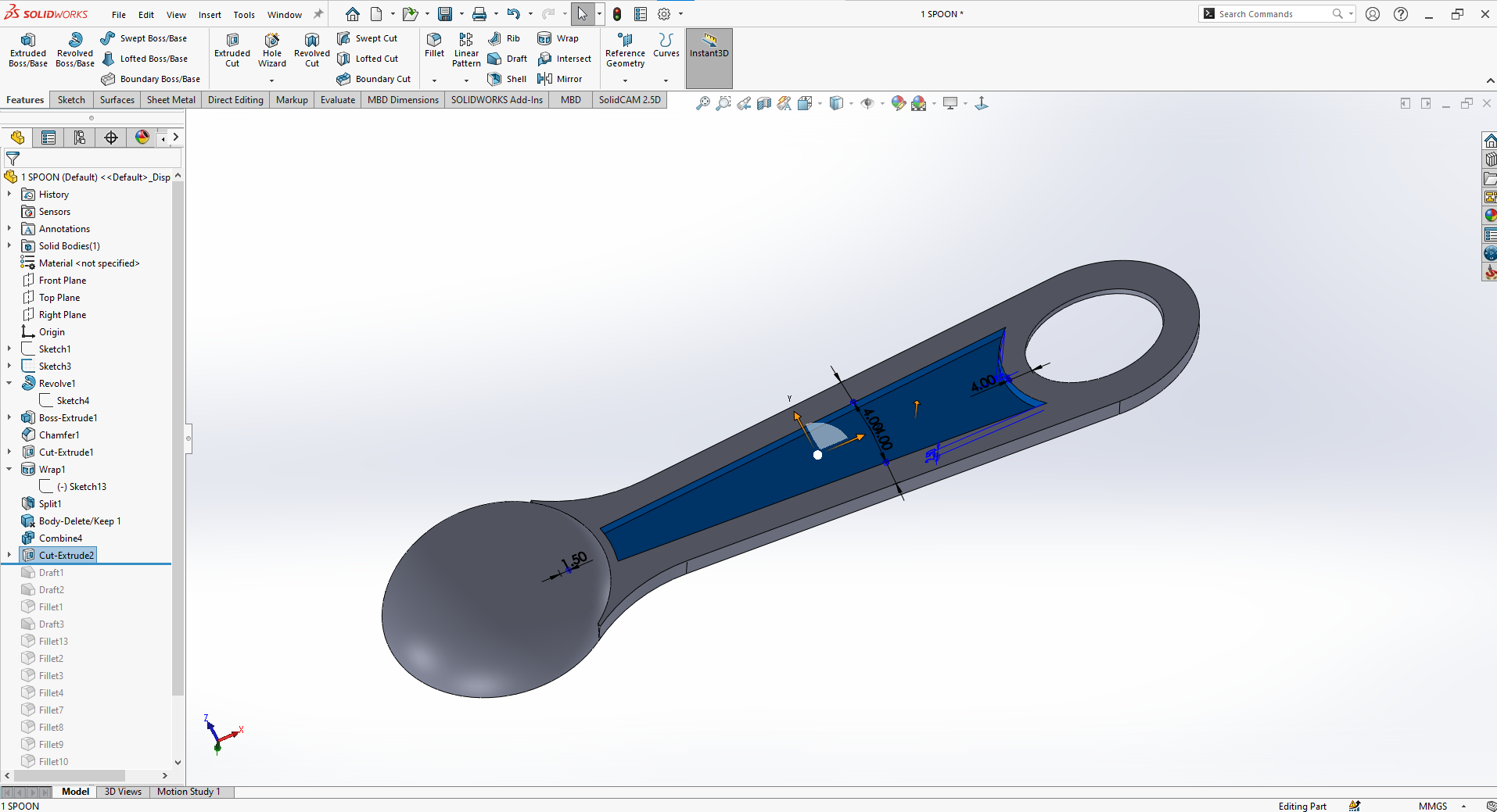
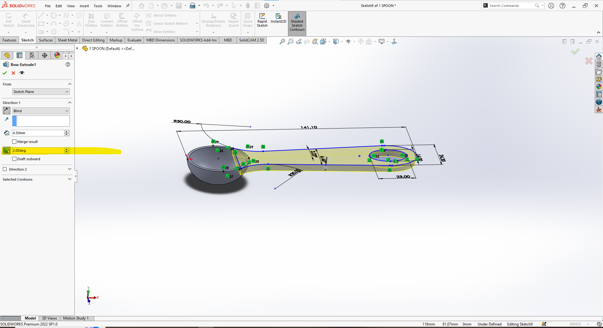
Figure 1: Design a Plastic Spoon


Wall Thickness

  • Uniformity is everything: Consistent wall thickness ensures balanced cooling, minimizes residual stresses, and prevents headaches like warping or sink marks.
  • Material matters: For example, aim for 1.2–3.5 mm with ABS, 0.8–3.0 mm with Polypropylene, and 1.0–4.0 mm with Polycarbonate. 
  • Avoid abrupt jumps: Smooth transitions between sections help the molten plastic flow evenly, avoiding internal voids and long cooling times.

Figure 2: Wall Thickness for the Spoon


Draft Angles
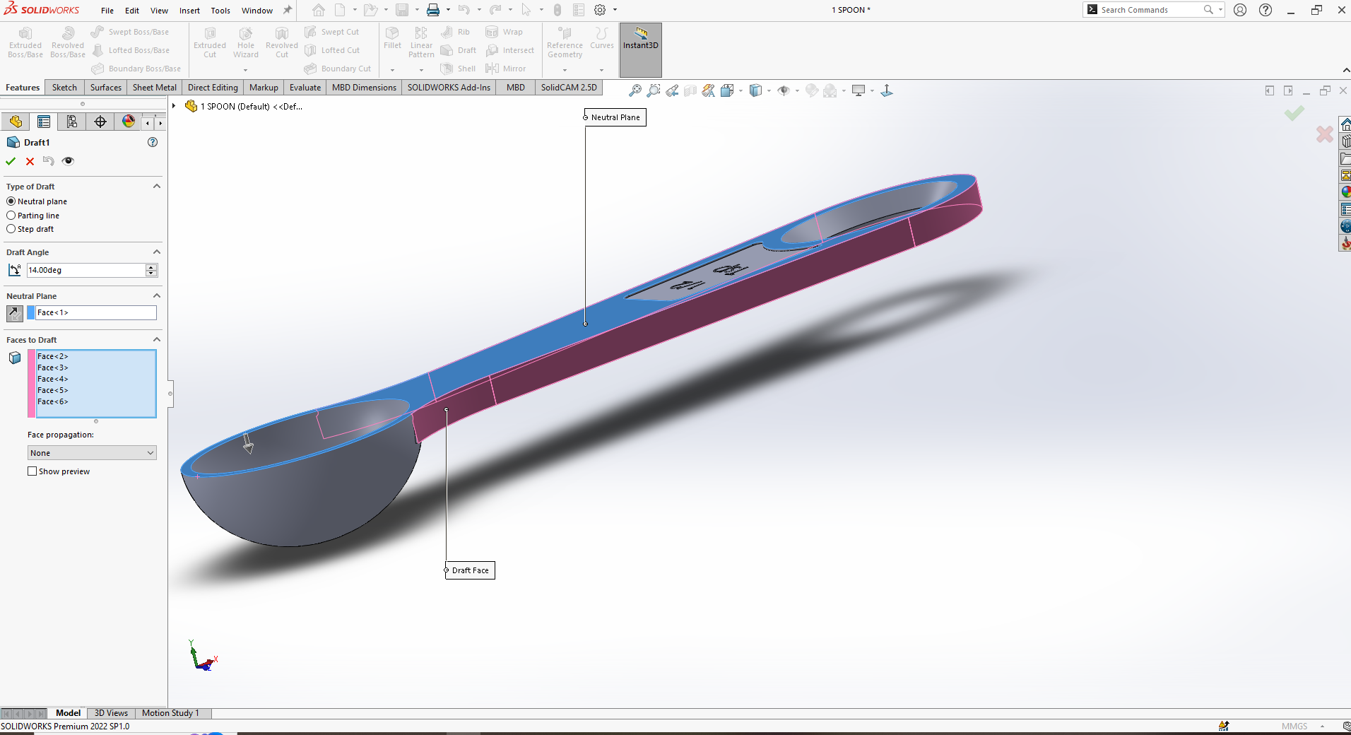
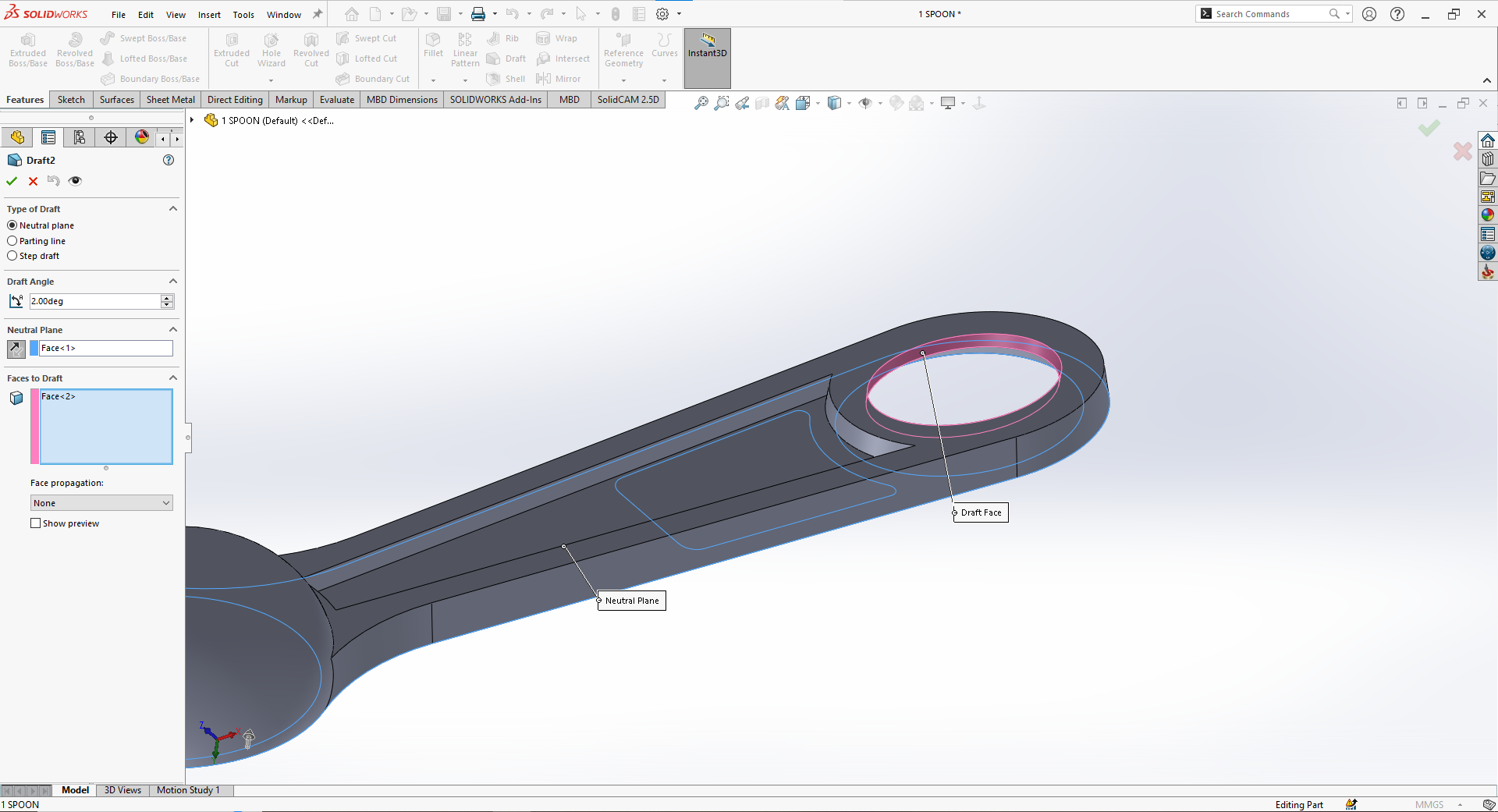
Draft angles might seem like a small detail, but they’re critical. Adding a 1–2° taper per side to vertical walls allows parts to eject smoothly without scratching or distorting.

  • Longer mold life: Draft also reduces wear and tear on the mold, protecting your tooling investment.

Figure 3: Adding Draft to the Plastic Spoon


Radii and Fillets

  • Sharp corners are stress concentrators and flow disruptors. Instead, aim for internal radii of at least 0.5× the wall thickness, helping plastic flow uniformly and improving the part’s mechanical strength.
  • These rounded features not only make your part stronger—they make it look better and eject more cleanly too.


Figure 4: Adding internal Radii to Part


Designing with Mold Ejection in Mind
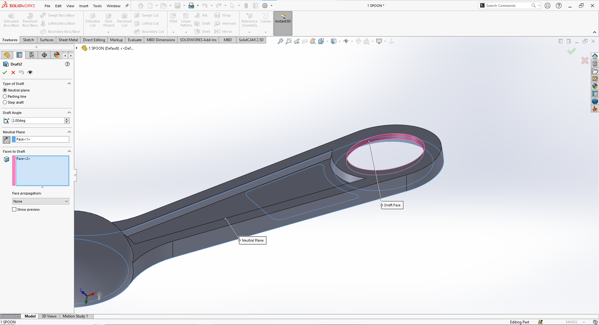
Even the best-looking design fails if it can’t release from the mold properly.


Figure 5: Draft face to help in Ejection of Part from Mold


Ejector Pins
Strategically placed ejector pins push your cooled part out without damaging it. Reinforce flat contact areas—called ejector pads—to spread the force evenly.

Mold Release Features
Incorporating draft and texture minimizes reliance on mold release agents, which keeps cycles cleaner and speeds up production.

Ribs and Bosses – Strength Without Bulk

Rather than bulking up walls to add strength, smart designers lean on ribs and bosses.

Figure 6: Ribs and Bosses Features to Part

Ribs

  • Designed correctly, ribs add rigidity without excess weight. Keep them 50–70% of the adjoining wall thickness and limit height to about 3× that thickness.
  • Slight draft and rounded bases prevent sink marks and make ejection smoother.

Bosses

  • Bosses are the go-to for accepting screws or inserts, but keep them at roughly 60% of adjacent wall thickness to avoid cosmetic flaws.
  • Fillets and supporting ribs reinforce these structures against stress.

Conclusion to Part 1
Designing for injection molding is an art that balances geometry, mechanics, and process constraints. By embracing best practices around wall thickness, draft, radii, ribs, and bosses, you’re setting your part up for consistent quality and cost-efficient manufacturing.

Stay tuned for Part 2, where we’ll dive into material selection, mold design strategies, and how to make sure your brilliant design stands up to real-world demands.


From Idea to Mold – The Essentials of Injection Molded Part Design (Part 2)

Introduction

In Part 1, we laid the groundwork by exploring how geometry, wall thickness, draft angles, ribs, and bosses shape the manufacturability and performance of injection molded parts. Now in Part 2, we continue the journey—diving into advanced design elements that ensure your parts assemble properly, mold efficiently, maintain their aesthetic appeal, and meet tight tolerances after cooling.


Snap Fits & Assembly Features

Many plastic parts are ultimately destined to be joined with others. Designing these joining features up front is crucial for reducing assembly costs and ensuring reliable performance.

Snap Fits

Snap fits are a popular way to assemble parts without fasteners or adhesives. These cantilever-like features flex during assembly and then “snap” into place.

  • Deflection matters: Typical designs allow for 0.5mm to 2mm deflection with a return angle of 30°–45° for secure engagement.
  • Durability: Properly designed snap fits minimize the risk of stress cracking over repeated use.

Other Assembly Features

  • Guide pins, keyways, and chamfers simplify alignment, ensuring parts fit together precisely every time.
  • Incorporating these during the initial design phase avoids costly secondary operations or rework later.


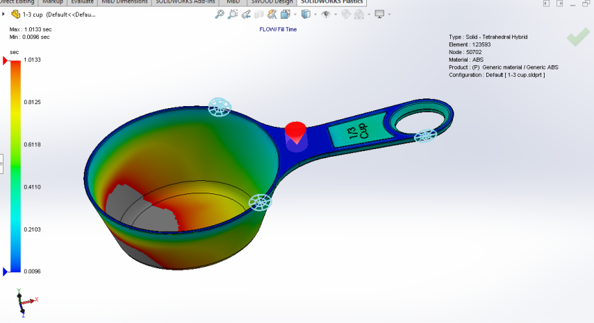
Mold Flow & Fill Analysis

Even well-designed parts can run into issues once molten plastic starts flowing through the mold.

  • Flow length-to-thickness ratio: Keeping this optimized ensures the plastic fills evenly without excessive pressure, reducing the risk of short shots or voids.
  • Weld lines: These are points where flow fronts meet and can create weak spots. Avoid placing critical features or load-bearing elements near these zones.

Figure 1: Mold Flow Analysis of a Plastic Part

Running a mold flow simulation before cutting steel helps visualize how the material fills the cavity, allowing you to adjust gate locations, wall thickness, or flow paths proactively.

Cooling & Shrinkage Considerations

Once filled, the plastic must cool. This stage often introduces dimensional changes that, if not accounted for, can lead to warping or out-of-spec parts.

  • Cooling time: Adequate cooling is essential to maintain tolerances. Designs with uniform wall thickness cool more evenly, reducing internal stresses.
  • Shrinkage: Most thermoplastics shrink between 0.1% and 2% as they cool. Each material behaves differently, so designers must adjust dimensions in CAD or collaborate closely with mold makers to compensate.

Aesthetics & Branding Features

Injection molding also offers opportunities to build aesthetics and brand identity right into the part.

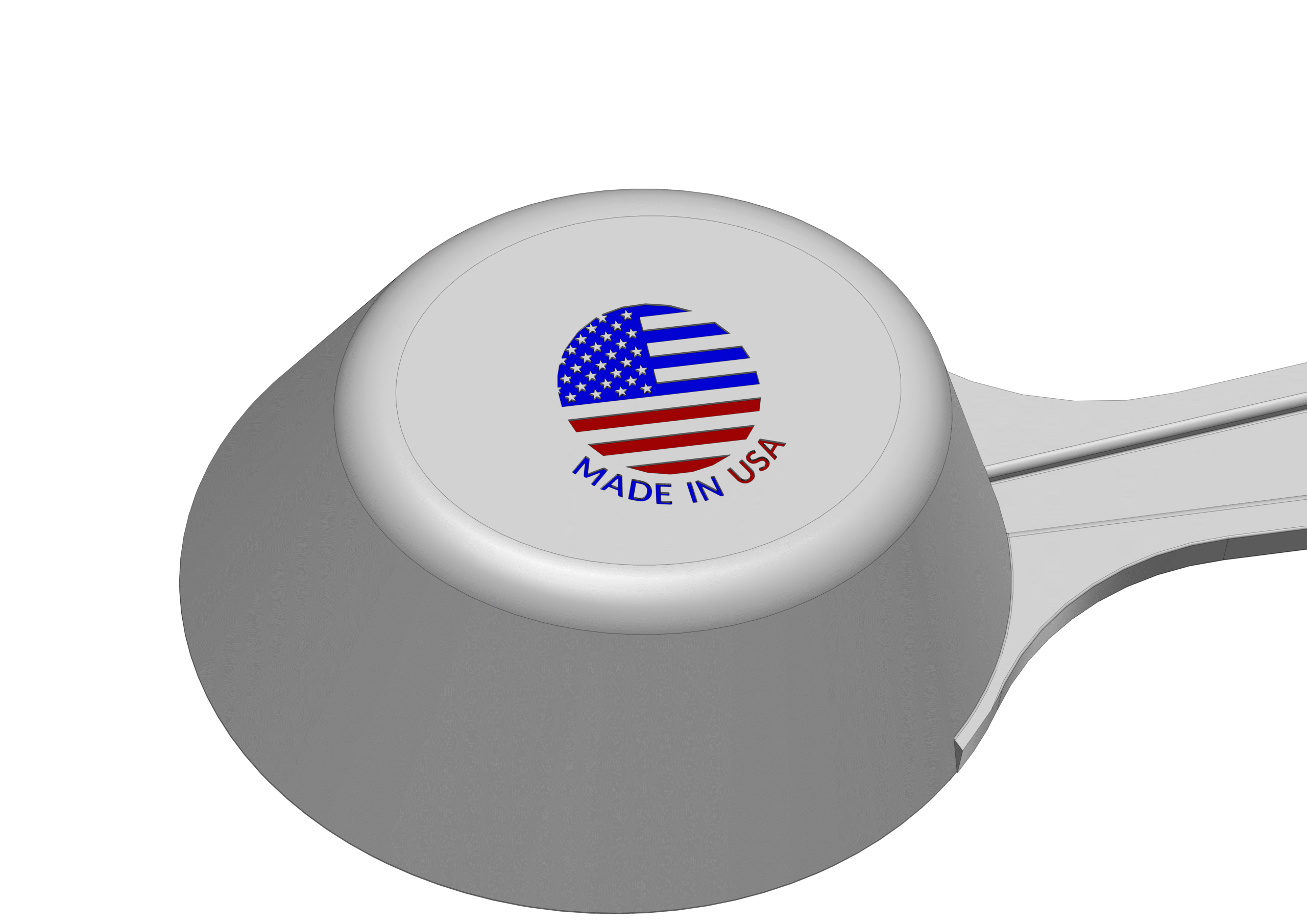
Logos & Markings

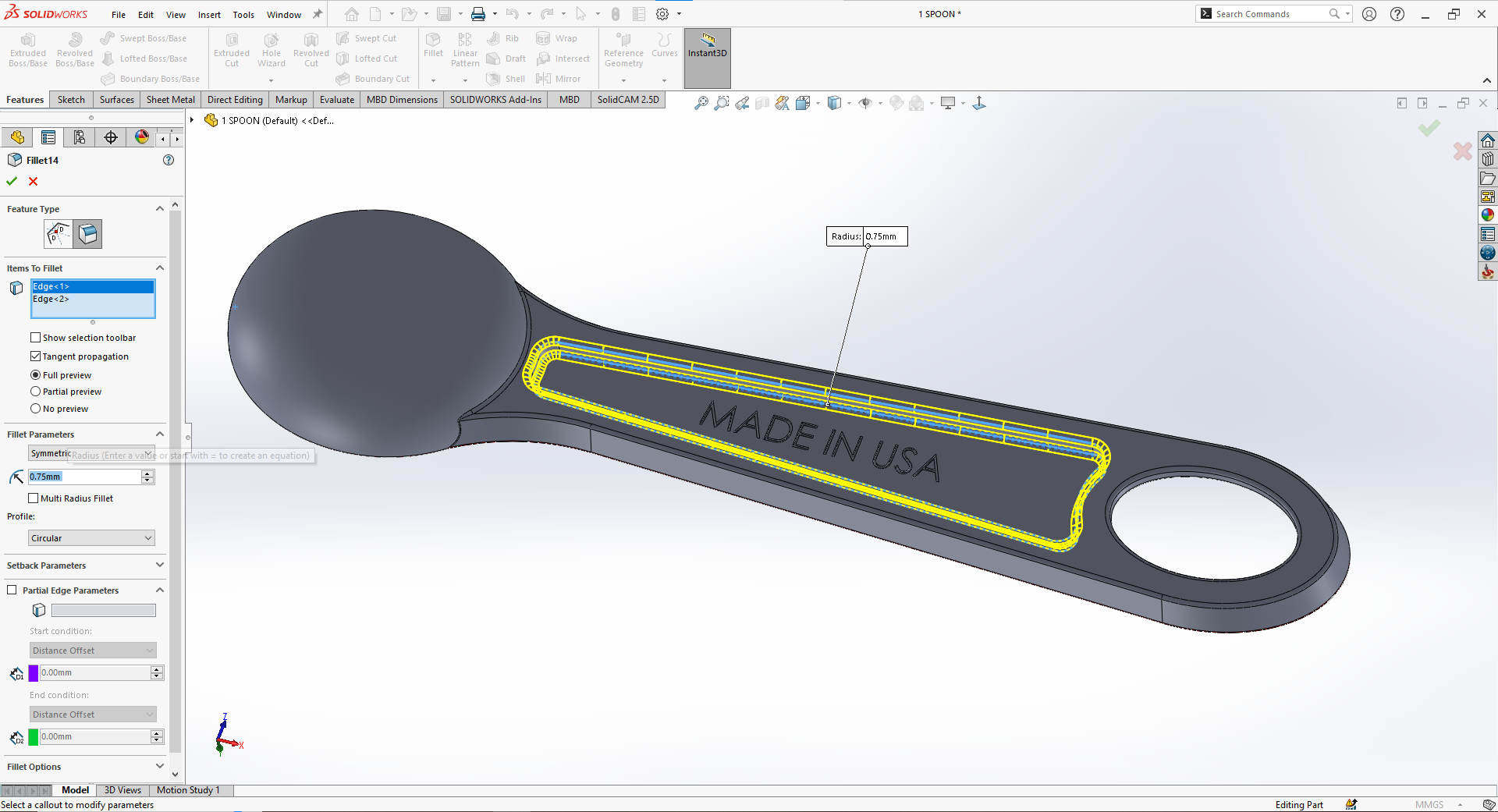
  • For molded-in logos, ensure a minimum line width of 0.25mm and depth around 0.1–0.3mm.
  • Place them on flat, non-critical surfaces and apply at least a 1° draft to aid ejection and maintain clarity.

Figure 2: Aesthtics of adding Made in USA to plastic part

Surface Textures

  • Texturing not only enhances appearance but can hide minor imperfections, add grip, or improve scratch resistance.
  • Discuss these options early with your toolmaker so they can apply etching or polishing directly to the mold.

Conclusion to Part 2

Designing injection molded parts is more than just ensuring they fill and eject properly—it’s about thinking through how they snap together, look on the shelf, and maintain critical dimensions even after cooling. By focusing on these advanced considerations—snap fits, flow analysis, shrinkage planning, and aesthetics—you create parts that excel in form, function, and brand impact.

With this two-part guide, you now have a comprehensive blueprint for moving from concept sketches to robust, production-ready molded components.


How We Make a Quality Plastic Waste Bin at Jimdi Plastics

At Jimdi Plastics, we take pride in delivering durable, high-quality products — and our 35-quart plastic waste bin is a perfect example. Manufactured right here in our facility using advanced injection molding processes, this waste bin showcases the care and precision we bring to every project.

We produce this bin on our 700-ton Van Dorn injection molding press, which cycles once every 60 seconds, enabling us to meet demanding production schedules while maintaining strict quality standards.

What We Look For

Our quality team inspects each waste bin to ensure:
Clean, uniform color
A completely formed rim
Smooth, consistent exterior walls
No flash or excess material at the top

Thin-walled parts like this waste bin naturally create high side-wall pressures, which can lead to uneven wall thickness. Through careful process optimization, we’ve overcome these challenges, eliminating variations and consistently achieving flawless results.

Going Beyond a Simple Waste Bin

While it might appear to be just a standard household item, this waste bin is a testament to the expertise and dedication Jimdi Plastics brings to every job — whether it’s consumer products, office furniture components, or automotive and industrial applications. We’re driven to deliver precision-molded products that customers can rely on, cycle after cycle.

Powered by Partnership

At Om Raj Tech, we proudly represent Jimdi Plastics, connecting businesses across industries with this level of dependable, U.S.-based manufacturing capability. Together, we offer our customers the advantage of high-quality injection molding, supported by responsive engineering teams and a streamlined production process.

If you’re looking to source injection molded parts — whether simple or complex — trust Om Raj Tech in partnership with Jimdi Plastics to bring your ideas to life with precision, consistency, and care.

From Concept to Production: Injection Molding Part Design Strategies That Work

Injection molding is one of the most widely used manufacturing processes for producing plastic parts. It offers high precision, scalability, and cost-effectiveness, making it a preferred method for industries ranging from consumer goods to automotive. However, designing parts for injection molding requires a deep understanding of the process, materials, and design principles. This guide provides expert insights into designing parts for injection molding, ensuring that your designs are manufacturable, efficient, and meet the required performance standards.

  • Table of Contents
  1. Introduction to Injection Molding
  2. Design Considerations for Injection Molding
  3. Material Selection for Injection Molding
  4. Design for Manufacturability (DFM)
  5. Tooling and Mold Design
  6. Surface Finishing and Textures
  7. Assembly and Post-Molding Operations
  8. Testing and Validation
  9. Sustainability in Injection Molding
  10. Cost Considerations and Optimization
  11. Case Studies and Examples
  12. Best Practices and Future Trends


  • Introduction to Injection Molding

Injection molding is a manufacturing process where molten plastic is injected into a mold cavity. Once the plastic cools and solidifies, the mold opens, and the part is ejected. This process is highly versatile and can produce parts with complex geometries, tight tolerances, and high volumes.


  • Key Components of Injection Molding
  1. Plastic Material: The raw material used, typically thermoplastic or thermosetting polymers.
  2. Mold: A metal cavity that shapes the molten plastic into the desired form.
  3. Injection Unit: Responsible for melting the plastic and injecting it into the mold.
  4. Ejection System: Mechanism that removes the part from the mold after cooling.


  • Advantages of Injection Molding

High Volume Production: Suitable for producing large quantities of parts.

Complex Geometries: Capable of creating intricate shapes and features.

Low Labor Costs: Automated process reduces the need for manual intervention.

Material Efficiency: Minimal waste compared to other manufacturing methods.


  • Common Applications

– Consumer goods (e.g., household items, electronics)

– Automotive components

– Medical devices

– Packaging


  • Design Considerations for Injection Molding

Designing parts for injection molding requires careful consideration of several factors to ensure manufacturability, functionality, and cost-effectiveness.


  • Part Geometry

Wall Thickness: In injection molding, wall thickness plays a crucial role in ensuring part quality, strength, and manufacturability. Ideally, walls should be uniform to promote consistent cooling and prevent defects like warping, sink marks, or internal stresses. Recommended thickness varies by material—ABS (1.2–3.5 mm), Polypropylene (0.8–3.0 mm), and Polycarbonate (1.0–4.0 mm). Avoid abrupt changes in thickness; instead, use gradual transitions or tapers to maintain flow consistency. Overly thick sections can lead to long cooling times and defects, while very thin walls may result in incomplete filling. Always balance strength, material flow, and mold ability when deciding wall  thickness for optimal injection-molded part performance.


Draft Angles: In injection molding, a draft angle is the slight taper applied to vertical surfaces of a part to facilitate easy ejection from the mold. Without adequate draft, parts can stick, causing damage or requiring excessive ejection force. A typical draft angle ranges from 1° to 2° per side, but more may be needed for textured or deep parts. Proper draft improves mold longevity and ensures smooth part release, reducing defects and production delays. All faces perpendicular to the mold opening direction should have draft applied. Designing with draft in mind is essential for moldability, efficiency, and consistent part quality.

Radius and Fillets: In injection molding, radii and fillets are rounded transitions between surfaces that reduce stress concentrations, improve material flow, and enhance part strength. Sharp corners, especially internal ones, can cause weak points, warping, or incomplete filling. Adding fillets (internal curves) and radii (external curves) helps maintain uniform wall thickness and reduces wear on the mold. A good rule is to use an internal radius of at least 0.5× the wall thickness and match external radii accordingly. These smooth transitions also aid in ejection and overall part aesthetics. Proper use of fillets and radii is essential for durable, high-quality molded parts.

  1. Material Selection

Thermoplastics: Commonly used due to their re-meltable nature (e.g., PP, ABS, PC).

Thermosets: Used for high-temperature applications but are not reusable once set.

Additives: Include fillers, colorants, or reinforcements based on the desired properties.


  1. Tolerances

Dimensional Tolerance: Typically ±0.1mm to ±0.5mm, depending on the material and part size.

Surface Finish: Specify surface roughness (e.g., Ra 1.6 to Ra 12.5) based on the application.


  1. Ejection and Mold Release

Ejector Pins: Ejector pins are critical components in injection molding that push the finished part out of the mold once it has cooled and solidified. Located on the mold’s core side, they apply a controlled force to release the part without causing damage or deformation. Ejector pins are typically round and leave small, often visible marks on non-cosmetic surfaces. Proper pin placement is crucial to avoid warping or sticking, especially on large or thin-walled parts. Designers should provide flat, reinforced areas—called ejector pads—for pin contact. Effective ejection ensures consistent cycle times, part quality, and mold longevity in high-volume manufacturing.

Mold Release: Design features to minimize the need for mold release agents, such as textured surfaces or draft angles.

  1. Ribs and Bosses

Ribs: Ribs in injection molding are thin, protruding features used to reinforce plastic parts without adding excessive material or increasing wall thickness. They enhance structural rigidity, prevent bending, and support other features like bosses or mounting points. To avoid sink marks and warping, ribs should be designed with proper proportions: typically 50–70% of the adjacent wall thickness and no taller than three times that thickness. Draft angles of 0.5–1° and rounded bases help ensure smooth ejection and reduce stress concentrations. Well-designed ribs improve mechanical performance while maintaining moldability, ensuring strong, lightweight, and visually acceptable injection-molded components.

Bosses: Bosses in injection molding are raised cylindrical features typically used for assembly purposes, such as accommodating screws, inserts, or aligning parts. They should be designed with wall thickness no more than 60% of the adjoining wall to avoid sink marks and warping. Adding fillets at the base and reinforcing them with ribs or gussets enhances strength. Proper draft angles (typically 0.5–1°) help with ejection. Well-designed bosses improve part functionality, structural support, and manufacturability.

  1. Holes and Threads

Hole Diameter: In injection molding, hole diameter must be carefully designed to ensure moldability and part strength. Small holes can be difficult to mold accurately, while large holes may weaken the structure. A minimum diameter of 1 mm is recommended, depending on material and wall thickness. Holes should be placed with enough spacing from edges and other features to prevent stress concentration. For deep holes, core pins are used, and slight draft may be added to aid ejection and reduce wear.

Threads: In injection molding, thread diameter must be designed to ensure accurate molding and part strength. External threads are easier to mold than internal ones and should include a draft angle of 1–2° for smooth ejection. For internal threads, collapsible cores or unscrewing mechanisms may be required, increasing mold complexity. Threads should be coarse rather than fine to ensure proper filling and durability. The minimum recommended thread diameter is typically 5 mm, with sufficient clearance to avoid weak walls or distortion.


  1. Snap Fits and Assembly Features

Snap Fits: Design cantilever beams with adequate deflection (0.5mm to 2mm) and return angle (30° to 45°).

Assembly Features: Incorporate alignment features (e.g., guide pins, keyways) for ease of assembly.

  1. Mold Flow and Fill Analysis

Flow Length-to-Thinness Ratio: Optimize the flow path to ensure even filling and minimize material pressure.

Weld Lines: Avoid placing critical features where weld lines may form, as they can weaken the part.

  1. Cooling and Shrinkage

Cooling Time: Ensure sufficient cooling time to prevent warping and dimensional inaccuracies.

Shrinkage: Account for material shrinkage (typically 0.1% to 2%) in your design.

  1. Aesthetics and Branding


Logos and Markings: In injection molding, logo engraving should be designed with clear, moldable dimensions to ensure readability and ease of manufacturing. The minimum line width (diameter) for engraved features is typically 0.25 mm, depending on the material and mold precision. Engravings should not be too deep—usually 0.1 to 0.3 mm—to avoid sink marks and ensure smooth ejection. Placement on flat, non-critical surfaces is ideal. Adequate draft angles (at least 1°) help prevent damage during demolding and improve logo clarity.

  • Material Selection for Injection Molding

The choice of material is critical for the performance, cost, and manufacturability of your part.

  • Common Materials
  1. Polypropylene (PP): Lightweight, flexible, and chemical-resistant.
  2. Acrylonitrile Butadiene Styrene (ABS): Impact-resistant and suitable for high-temperature applications.
  3. Polycarbonate (PC): Transparent, impact-resistant, and suitable for optical applications.
  4. Polyethylene (PE): Low-cost, flexible, and chemical-resistant.
  5. Polyester (PET): High-strength, rigid, and suitable for packaging.
  • Material Properties to Consider

Mechanical Properties: Tensile strength, impact resistance, and flexural modulus.

Thermal Properties: Heat deflection temperature (HDT) and thermal conductivity.

Chemical Resistance: Compatibility with chemicals and cleaning agents.

Optical Properties: Transparency, gloss, and UV resistance.

  • Additives and Fillers

Reinforcements: Glass fibers for increased strength and stiffness.

Fillers: Minerals like calcium carbonate to reduce material costs.

Colorants: Pigments or masterbatches for custom colors.

UV Stabilizers: To prevent degradation from UV exposure.

  • Sustainability Considerations

Recyclability: Choose materials that are recyclable or biodegradable.

Bioplastics: Consider PLA (Polylactic Acid) or PHA (Polyhydroxyalkanoates) for eco-friendly applications.

Material Efficiency: Optimize part weight and thickness to minimize material usage.

  • Design for Manufacturability (DFM)

Design for Manufacturability (DFM) is a critical aspect of injection molding that ensures your part can be produced efficiently and cost-effectively.

  • Key DFM Principles
  1. Simplify the Design: Avoid unnecessary complexity that could increase tooling costs or lead to manufacturing defects.
  2. Minimize Undercuts: Undercuts require side actions in the mold, which increase tooling complexity and cost.
  3. Avoid Thin Walls: Ensure wall thickness is consistent and within recommended limits to prevent warping and sink marks.
  4. Use Standard Features: Standardize features like bosses, ribs, and snaps to reduce design variability.
  • Moldability Analysis

Flow Analysis: Use simulation tools to analyze how molten plastic flows into the mold cavity.

Pressure Drop: Ensure that the pressure drop is within acceptable limits to avoid material degradation.

Cooling Analysis: Optimize cooling channels to ensure uniform cooling and minimize warping.

  • Design for Assembly (DFA)

Snap Fits: Use snap fits to eliminate the need for fasteners.

Alignment Features: Incorporate guide pins, keyways, or chamfers to facilitate easy assembly.

Modular Design: Design parts that can be easily assembled into a complete product.

  • Cost Reduction Strategies

Reduce Material Usage: Optimize part weight and thickness to minimize material costs.

Simplify Tooling: Avoid complex mold features that increase tooling costs.

Increase Production Volume: Take advantage of economies of scale by producing larger batches.

  • Tooling and Mold Design

The mold is a critical component of the injection molding process, and its design directly impacts the quality, cost, and lead time of your part.

  • Key Components of a Mold
  1. Cavity: The part of the mold that shapes the plastic into the desired form.
  2. Core: The part of the mold that creates holes or recesses in the part.
  3. Runner System: Channels that direct molten plastic from the injection unit to the mold cavity.
  4. Gates: Points where molten plastic enters the mold cavity.
  5. Ejector Pins: Mechanisms that push the part out of the mold after cooling.


  • Mold Types
  1. Single-Cavity Mold: Produces one part per cycle. Ideal for low-volume production.
  2. Multi-Cavity Mold: Produces multiple parts per cycle. Ideal for high-volume production.
  3. Family Mold: Produces multiple parts of similar size or shape. Reduces tooling costs.
  4. Hot Runner Mold: Uses insulated runners to keep the plastic molten between shots. Reduces material waste.


  • Mold Materials
  1. Steel: Most common mold material due to its durability and cost-effectiveness.
  2. Aluminum: Used for prototype molds or low-volume production due to its faster machining time.
  3. Beryllium Copper: Used for high-wear areas due to its high thermal conductivity.


  • Mold Surface Finish

Polishing: Improves part quality and reduces mold wear.

Texturing: Creates surface textures for aesthetic or functional purposes.

Coating: Applies wear-resistant or corrosion-resistant coatings to critical areas.


  • Mold Maintenance

Cleaning: Regularly clean the mold to prevent contamination and material buildup.

Lubrication: Lubricate moving parts to reduce wear and tear.

Inspection: Inspect the mold for damage or wear and perform repairs as needed.


  • Surface Finishing and Textures

Surface finishing and textures play a crucial role in the aesthetics and functionality of injection-molded parts.


  • Common Surface Finishes
  1. Polished Finish: Achieved by polishing the mold cavity to a high gloss. Ideal for optical applications.
  2. Textured Finish: Creates a specific surface texture for grip, aesthetics, or functionality.
  3. Matte Finish: Provides a dull, non-reflective surface. Ideal for hiding mold marks or imperfections.
  4. Etched Finish: Creates a fine, detailed texture using chemical etching.


  • Texture Patterns
  1. Fine Texture: Provides a smooth, low-gloss surface.
  2. Medium Texture: Offers a balanced combination of aesthetics and functionality.
  3. Coarse Texture: Ideal for applications requiring high grip or durability.


  • Functional Textures

Grip Textures: Used on handles, grips, and other areas requiring traction.

Ventilation Textures: Create airflow or drainage in applications like filters or vents.

Aesthetic Textures: Enhance the visual appeal of the part.


  • Application Methods
  1. Mold Texturing: Textures are incorporated directly into the mold cavity.
  2. Post-Molding Texturing: Textures are applied after molding using processes like laser etching or pad printing.
  3. Insert Molding: Textures are molded into inserts that are then assembled into the final part.


  • Assembly and Post-Molding Operations

Many injection-molded parts require additional assembly or post-molding operations to meet their functional requirements.


  • Assembly Methods
  1. Snap Fits: Use cantilever beams or other snap-fit features to eliminate the need for fasteners.
  2. Ultrasonic Welding: Join parts using high-frequency vibrations to create a strong bond.
  3. Adhesive Bonding: Use adhesives to join parts, especially when different materials are involved.
  4. Screw or Rivet Assembly: Use mechanical fasteners for applications requiring high strength or adjustability.


  • Post-Molding Operations
  1. Printing: Apply labels, logos, or other graphics using screen printing, pad printing, or laser marking.
  2. Painting: Apply paint for aesthetic or functional purposes, such as color matching or UV resistance.
  3. Plating: Apply metal coatings for conductivity, corrosion resistance, or aesthetics.
  4. Machining: Perform secondary machining operations like drilling, tapping, or grinding for precision features.


  • Automation in Assembly

Robotic Assembly: Use robots to automate repetitive tasks like screw driving or welding.

Vision Systems: Use vision systems to inspect and guide assembly operations.

Conveyor Systems: Use conveyor systems to move parts through the assembly line efficiently.


  • Design for Assembly (DFA)

Simplify the Design: Minimize the number of parts and fasteners to reduce assembly time and cost.

Modular Design: Design parts that can be easily assembled into a complete product.

Alignment Features: Incorporate guide pins, keyways, or chamfers to facilitate easy alignment during assembly.


  • Testing and Validation

Before moving to mass production, it’s essential to test and validate your design to ensure it meets the required performance, safety, and quality standards.


  • Types of Testing
  1. Mechanical Testing: Evaluate the part’s strength, stiffness, and impact resistance.
  2. Thermal Testing: Test the part’s performance under extreme temperatures.
  3. Chemical Resistance Testing: Assess the part’s resistance to chemicals and cleaning agents.
  4. Optical Testing: Evaluate the part’s clarity, gloss, and UV resistance.
  5. Functional Testing: Test the part’s functionality in its intended application.


Rapid Prototyping: Use 3D printing or CNC machining to create prototypes for testing.

Design Iteratio: Refine the design based on test results and feedback.

Design Freeze: Finalize the design once all issues have been resolved.


  • Quality Control

Inspection: Regularly inspect parts for defects or variations.

Dimensional Measurement: Measure critical dimensions to ensure compliance with specifications.

Statistical Process Control (SPC): Monitor the production process to maintain consistent quality.


As environmental concerns grow, designing sustainable injection-molded parts is becoming increasingly important.


  • Key Sustainability Considerations
  1. Material Selection: Choose materials that are recyclable, biodegradable, or made from renewable resources.
  2. Material Efficiency: Optimize part weight and thickness to minimize material usage.
  3. Energy Efficiency: Design parts that can be produced using less energy and water.
  4. End-of-Life Design: Design parts for disassembly, recycling, or biodegradation.


  • Bioplastics

PLA (Polylactic Acid): A biodegradable thermoplastic made from renewable resources like corn starch or sugarcane.

PHA (Polyhydroxyalkanoates): A biodegradable thermoplastic produced from bacterial fermentation.

PBAT (Polybutylene Adipate-co-Butylene Terephthalate): A biodegradable thermoplastic used for flexible applications.


  • Recyclable Materials

Recycled Plastics: Use post-consumer recycled (PCR) or post-industrial recycled (PIR) materials.

Material Identification: Use material identification codes to facilitate sorting and recycling.


  • Design for Recyclability

Simplify the Design: Avoid complex geometries or multiple materials that complicate recycling.

Material Separation: Design parts that can be easily disassembled and separated into different materials.

Avoid Contaminants: Minimize the use of additives, coatings, or adhesives that can contaminate recycled materials.


  • Cost Considerations and Optimization

Understanding the cost drivers in injection molding is essential for optimizing your design and reducing production expenses.


  • Key Cost Drivers
  1. Tooling Costs: The cost of designing and building the mold is a significant upfront expense.
  2. Material Costs: The cost of the plastic material used to produce the part.
  3. Production Volume: Higher production volumes reduce the per-unit cost due to economies of scale.
  4. Complexity: Complex geometries, undercuts, and multiple cavities increase tooling and production costs.


  • Cost Reduction Strategies
  1. Simplify the Design: Avoid unnecessary complexity that increases tooling and production costs.
  2. Use Standard Features: Standardize features like bosses, ribs, and snaps to reduce design variability.
  3. Optimize Material Usage: Minimize material waste by optimizing part weight and thickness.
  4. Use Recycled Materials: Incorporate recycled plastics to reduce material costs.
  5. Increase Production Volume: Take advantage of economies of scale by producing larger batches.


  • Total Cost of Ownership (TCO)

Material Costs: The cost of the plastic material over the product’s lifecycle.

Tooling Costs: The upfront cost of designing and building the mold.

Production Costs: The cost of producing the part, including labor, energy, and overhead.

Post-Molding Costs: The cost of additional operations like assembly, painting, or packaging.

Warranty and Repair Costs: The cost of repairing or replacing defective parts.


  • Case Studies and Examples

Real-world examples provide valuable insights into the challenges and opportunities of designing parts for injection molding.


  • Case Study 1: Consumer Electronics Housing

Challenge: Design a lightweight, impact-resistant housing for a portable electronic device.

Solution: Use ABS for its high impact resistance and process ability. Incorporate ribs and gussets for added stiffness without increasing material usage.

Outcome: A durable, cost-effective housing that meets the required performance and aesthetic standards.


  • Case Study 2: Medical Device Component

Challenge: Design a clear, autoclavable component for a medical device.

Solution: Use PC for its transparency and high heat resistance. Incorporate textured surfaces for grip and alignment features for easy assembly.

Outcome: A component that meets strict medical standards for clarity, sterility, and functionality.


  • Case Study 3: Automotive Part

Challenge: Design a lightweight, heat-resistant part for an automotive application.

Solution: Use a glass-filled PA6 for its high strength, stiffness, and heat resistance. Optimize the design for minimal material usage and easy assembly.

Outcome: A cost-effective, high-performance part that meets the demanding requirements of the automotive industry.


  • Best Practices and Future Trends

Adhering to best practices and staying informed about future trends ensures that your designs remain competitive and innovative.


  • Best Practices
  1. Collaborate with Mold Makers: Work closely with mold makers to ensure your design is manufacturable.
  2. Use Simulation Tools: Utilize mold flow and structural analysis tools to optimize your design.
  3. Consider Sustainability: Design parts with sustainability in mind, using recyclable or biodegradable materials.
  4. Iterate and Refine: Continuously refine your design based on testing and feedback.


  • Future Trends
  1. Advanced Materials: Development of new materials with enhanced properties, such as self-healing plastics.
  2. Digital Manufacturing: Increased use of digital tools for design, simulation, and production.
  3. Circular Economy: Focus on designing parts for recyclability, reusability, and biodegradability.
  4. Additive Manufacturing: Integration of additive manufacturing techniques with injection molding for hybrid production methods.

By following the insights and guidelines outlined in this guide, you can design injection-molded parts that are functional, cost-effective, and sustainable. Whether you’re a seasoned designer or just starting out, understanding the principles of injection molding will empower you to create innovative solutions that meet the demands of modern manufacturing.
Design Considerations for Successful Plastic Injection Molding

Designing parts for plastic injection molding requires careful consideration of various factors to ensure successful manufacturing and optimal part performance. In this article, we will delve into the key design considerations that play a crucial role in achieving successful plastic injection molding. Understanding these considerations, such as part geometry, draft angles, wall thickness, and gating techniques, will help you design parts that are both manufacturable and meet your functional requirements.

1. Part Geometry:

The geometry of a part has a significant impact on its moldability and overall quality. Here are some important considerations:

a. Avoiding Undercuts: Undercuts are features on a part that prevent its ejection from the mold. Designing parts with minimal or no undercuts simplifies the mold design and ensures easy ejection.

b. Ribs and Bosses: Incorporating ribs for added strength or bosses for fastener attachment requires careful design to avoid sink marks, warping, or part distortion during cooling and solidification.

c. Fillets and Radii: Incorporating fillets and radii at sharp corners reduces stress concentrations, improves material flow during molding, and enhances part strength.

2. Draft Angles:

Draft angles are tapered surfaces on the part that facilitate its ejection from the mold. Consider the following:

a. Required Draft Angle: Incorporating draft angles into your design is essential to prevent damage to the part or mold and ensure smooth ejection. Typically, a draft angle of 1-2 degrees is recommended, but it may vary depending on the part geometry and material.

b. Adding Draft to Vertical Walls: Vertical walls without draft angles can cause sticking, excessive friction, and part distortion during ejection. Adding draft angles simplifies the molding process and improves overall part quality.

3. Wall Thickness:

Proper wall thickness is crucial for achieving optimal part strength, dimensional stability, and efficient manufacturing:

a. Maintaining Uniform Wall Thickness: Variations in wall thickness can result in uneven cooling, sink marks, or warping. Design parts with consistent wall thickness to ensure uniform material flow and balanced cooling.

b. Consider Material Properties: Different plastic materials have specific recommendations for minimum and maximum wall thickness. Understanding the material’s flow characteristics and limitations is essential to design parts with appropriate wall thickness.

4. Gating Techniques:

The gate is the point of entry for molten plastic into the mold cavity. Choosing the right gating technique is essential for successful injection molding:

a. Proper Gate Placement: Gate location affects part quality, including gate vestige, filling patterns, and material flow. Selecting an appropriate gate location based on part geometry and material properties is crucial for achieving optimal results.

b. Gate Size and Design: The size and design of the gate impact material flow, pressure, and cooling. Gate size should be balanced to ensure adequate filling without excessive pressure or material wastage.

Conclusion:

Designing parts for successful plastic injection molding involves considering various factors that impact both manufacturability and part performance. By taking into account part geometry, draft angles, wall thickness, and gating techniques, you can design parts that are easier to mold, have better structural integrity, and meet your functional requirements. Collaborating with experienced design and manufacturing professionals will further enhance the effectiveness of your plastic injection molding projects. Remember, thoughtful design considerations lead to better outcomes in terms of quality, cost, and overall success in the injection molding process.

6 Strategies to Reduce Cost of Plastic Parts in Injection Molding

As a sourcing or purchasing manager, reducing costs while maintaining quality is one of your top priorities. When it comes to plastic injection molding, there are several strategies you can use to cut down expenses without sacrificing the performance of your plastic parts. Here are six practical ways to optimize costs in your plastic injection molding projects:

Key Cost Reduction Strategies:

  • Choose the Right Material: Opt for materials that offer the best balance between cost and performance.

  • Simplify the Design: Work with your design team to remove complex features that drive up production costs.

  • Improve Process Efficiency: Make small adjustments to the production process to increase output without additional resources.

  • Reduce Waste: Implement better material management to minimize waste and maximize material usage.

  • Work Closely with Suppliers: Negotiate better pricing and collaborate on cost-effective solutions.

  • Focus on Continuous Improvement: Regularly review and refine processes to keep reducing costs over time.

1. Choose the Right Material

Selecting the right material can make a big difference in your costs. For example, if you’re currently using a high-performance plastic that costs $10 per kilogram, consider whether a similar material that costs $8 per kilogram could do the job just as well. By switching to the less expensive material, you could reduce your material costs by 20%, all without compromising the quality of your parts.

This simple step can help you achieve significant savings, especially in large production runs.

Plastic Resin Price Index (paid subscription needed) : Plastic News Resin Prices North America

You may find the newsletter from Cody Bates useful for costing resins for your products.

2. Simplify the Design

The design of your plastic parts plays a huge role in the overall cost. For instance, if your part has a complex feature like an undercut that requires special tooling, it’s going to be more expensive to produce. By working with your design team to simplify the part—say, by removing the undercut—you could save thousands of dollars in tooling costs and make the production process faster and more efficient.

Simpler designs not only lower costs but also speed up production, allowing you to meet tight deadlines and reduce labor expenses.

3. Improve Process Efficiency

Improving how the injection molding process is carried out can also lead to cost savings. For example, if you can reduce the cooling time by just a few seconds per cycle, you can produce more parts in the same amount of time. Let’s say you currently produce 1,000 parts per day with a cycle time of 60 seconds. Cutting the cycle time by 5 seconds could boost your output by an additional 100 parts per day.

This means you’re getting more parts without spending more money on extra resources, effectively reducing your per-unit cost.

4. Reduce Waste

Waste during production is money lost. If you’re seeing a waste rate of 10% in your material usage, there’s room for improvement. By implementing better material management practices, optimizing the runner and gating systems, and reusing scrap material, you could cut your waste rate in half. For example, reducing waste from 10% to 5% in a production run that uses 1,000 kilograms of material per month could save you 50 kilograms of material.

Less waste means direct savings, which adds up over time, especially in high-volume production.

5. Work Closely with Suppliers

Building strong relationships with your suppliers can lead to cost reductions as well. For instance, negotiating better pricing or bulk purchase discounts on materials can help you save significantly. If your annual material cost is $500,000, even a small 5% discount could save you $25,000. Additionally, collaborating with tooling suppliers to find cost-effective solutions can lower your upfront costs and reduce maintenance expenses down the line.

Good supplier relationships are key to securing the best deals and finding cost-effective solutions that meet your needs.

6. Focus on Continuous Improvement

Continuous improvement isn’t just a buzzword—it’s a way to keep costs down over time. By regularly reviewing and refining your processes, you can identify areas where efficiency can be improved. For example, setting up a team to focus on process improvements could help you reduce overall manufacturing costs by 10%.

Ongoing efforts to streamline production will keep you ahead of the competition and help you meet your cost reduction targets year after year.

Conclusion

Reducing costs in plastic injection molding doesn’t have to mean compromising on quality. By focusing on smart material choices, simplified designs, process efficiency, waste reduction, supplier collaboration, and continuous improvement, you can achieve significant savings. As a sourcing or purchasing manager, these strategies will help you meet your cost targets, making your projects more profitable and your company more competitive.

4 Key Strategies for Quality Control in Plastic Injection Molding

As a sourcing or purchasing manager, ensuring that your plastic injection molding partners deliver consistent, high-quality products is crucial. When your supplier is ISO 9001 certified, you can be confident that they follow strict quality control measures to meet your exact specifications. This article outlines four key strategies that ISO 9001 certified companies use to ensure quality control in plastic injection molding, helping you make informed decisions that support your cost, quality, and timeline goals.

Key Quality Control Strategies:

  • Inspection Techniques: Utilize advanced tools and software to ensure every part meets your standards.

  • Process Monitoring: Maintain consistent quality with real-time monitoring and data analysis tools.

  • Traceability: Implement comprehensive systems to track every step of production and quickly correct any issues.

  • ISO 9001 Certification: Trust in the rigorous standards that certified companies uphold to deliver high-quality products consistently.

1. Inspection Techniques

Inspection is the first line of defense in ensuring product quality. ISO 9001 certified companies use a variety of inspection tools and techniques to catch defects or deviations early. Common tools and equipment include Coordinate Measuring Machines (CMM) for dimensional verification, optical comparators for visual inspections, and laser scanners for precise measurements. Automated inspection systems such as vision systems and high-speed cameras are also employed to inspect parts at various stages of production.

Software tools like Geometric Dimensioning and Tolerancing (GD&T) analysis programs help ensure that parts meet exact specifications. By combining these inspection techniques with ISO 9001 standards, companies can consistently produce parts that meet or exceed customer expectations.

For sourcing managers, this means fewer surprises and more consistent delivery of parts that meet your exact specifications.

What is a CMM?

2. Process Monitoring

Consistency in production is key to delivering reliable products, and process monitoring is essential in achieving this. ISO 9001 certification requires companies to implement real-time monitoring systems for key process parameters such as temperature, pressure, and cycle time. Tools like Supervisory Control and Data Acquisition (SCADA) systems allow for continuous monitoring and control of the manufacturing process, ensuring that any deviations are quickly identified and corrected.

Software solutions like Statistical Process Control (SPC) are used to analyze data trends and ensure that processes remain within specified limits. Injection molding machines equipped with process monitoring software can automatically adjust parameters to maintain consistent quality throughout production runs.

For you, this means your plastic parts will be produced with a high level of precision, ensuring reliability in every order.

What is a Supervisory Control and Data Acquisition?

Using SPC to improve performance.

3. Traceability

When quality issues arise, having a traceability system is essential for quickly identifying the source of the problem. ISO 9001 certified companies implement comprehensive traceability measures, utilizing systems like Enterprise Resource Planning (ERP) software to document every step of the production process—from raw material procurement to the final product. These systems often integrate barcode scanners and RFID tags to track parts and materials in real-time.

Document management tools like Manufacturing Execution Systems (MES) provide detailed records, including material certifications, inspection reports, and production logs, ensuring full traceability. This allows companies to efficiently manage recalls or corrective actions if necessary.

For sourcing managers, this level of traceability means confidence in the consistency of the parts you receive and the ability to quickly address any issues, protecting your supply chain from disruptions.

4. ISO 9001 Certification

Choosing an ISO 9001 certified plastic injection molding partner gives you the assurance that they are committed to maintaining high-quality standards. ISO 9001 is an internationally recognized standard for quality management systems, ensuring that companies adhere to a rigorous process of continuous improvement, customer focus, and regulatory compliance.

ISO 9001 certified companies often use quality management software (QMS) to streamline documentation, automate audit processes, and track improvement initiatives. In addition to these tools, methodologies like Total Quality Management (TQM) and Kaizen are implemented to foster a culture of ongoing excellence and continuous improvement.

For sourcing managers, working with an ISO 9001 certified supplier means reducing the risk of receiving subpar products, which in turn minimizes costly delays and ensures that your projects stay on track. ISO 9001 certification also enhances customer trust and opens doors to potential business opportunities by demonstrating a strong commitment to quality.

Get a copy of the ISO 9001 standard.

Conclusion

As a sourcing or purchasing manager, ensuring the quality and reliability of the plastic parts you procure is vital to your success. By partnering with an ISO 9001 certified plastic injection molding company that utilizes advanced tools, software, and processes for quality control, you can rely on their commitment to deliver consistent, high-quality products. These practices not only guarantee the consistency and reliability of the parts you need but also support your cost, quality, and timeline goals.

Trust in the expertise and standards of ISO 9001 certified companies, equipped with the latest technology and methodologies, to keep your supply chain running smoothly and your business thriving.

Comparative Analysis of Resin Transfer Molding vs. Other Composite Manufacturing Techniques for Off-Highway Applications

Composite materials have become essential in the off-highway sector, offering significant benefits such as reduced weight, increased strength, and improved durability. Resin Transfer Molding (RTM) is one of the leading methods for injection molding manufacturing composite components, but it is not the only option. This article provides a comparative analysis of RTM against other composite manufacturing techniques, such as vacuum infusion, hand lay-up, and autoclave molding, focusing on their respective advantages, challenges, and suitability for off-highway applications.

Resin Transfer Molding (RTM): Overview and Advantages

Resin Transfer Molding (RTM) is a closed-mold process that involves injecting molding resin into a mold containing a pre-formed fiber reinforcement. The process is well-known for producing high-quality, complex parts with excellent surface finishes. RTM offers several key advantages, particularly for off-highway applications:

  • Precision and Repeatability: RTM allows for precise control over resin flow and fiber placement, resulting in highly consistent and repeatable parts. This precision is crucial for off-highway components that must meet stringent performance standards.

  • Complex Geometry: RTM can produce parts with complex shapes and integrated features, making it ideal for manufacturing intricate components such as vehicle body panels, structural parts, and enclosures.

  • Surface Finish: The closed-mold nature of RTM results in a smooth surface finish on both sides of the part, reducing the need for post-processing and enhancing the aesthetic appeal of visible components.

However, RTM also presents some challenges, including the need for precise mold design and the potential for high tooling costs, especially for low-volume production runs.

Vacuum Infusion: A Flexible Alternative

Vacuum infusion is another closed-mold process, similar to RTM, but with some distinct differences. In vacuum infusion, the resin is drawn into the mold using vacuum pressure, rather than being injected under pressure as in RTM.

  • Lower Tooling Costs: Vacuum infusion typically requires less expensive tooling compared to RTM, making it a more cost-effective option for lower-volume production runs or large parts.

  • Material Flexibility: The vacuum infusion process can accommodate a wide range of fiber types and resin systems, offering flexibility in material selection based on the specific needs of the application.

  • Improved Fiber Wet-Out: The vacuum pressure helps to ensure complete fiber wet-out, which can enhance the mechanical properties of the final part.

However, vacuum infusion may not be as precise as RTM, particularly for parts with very complex geometries. The surface finish is also typically not as smooth as what can be achieved with RTM, which may require additional finishing processes.

Hand Lay-Up: Traditional and Cost-Effective

Hand lay-up is one of the oldest and simplest composite manufacturing techniques. It involves manually placing layers of fiber reinforcement in an open mold and applying resin by hand.

  • Low Capital Investment: Hand lay-up requires minimal equipment and tooling, making it the most cost-effective option for small-scale production and prototyping.

  • Flexibility in Design: The process is highly adaptable, allowing for on-the-fly adjustments to fiber orientation and resin application, which can be beneficial for custom or one-off parts.

However, hand lay-up is labor-intensive and less consistent than automated processes like RTM. The quality of the final part is highly dependent on the skill of the operator, and the process is generally unsuitable for high-volume production due to its slow cycle times.

Autoclave Molding: High-Performance Composites

Autoclave molding is a process used to produce high-performance composite parts, particularly in aerospace and defense applications. The process involves placing a resin-impregnated fiber preform into a mold, which is then cured under heat and pressure in an autoclave.

  • Superior Mechanical Properties: The combination of high pressure and temperature during the autoclave process results in parts with exceptional mechanical properties, including high strength and stiffness.

  • High-Quality Surface Finish: Like RTM, autoclave molding can produce parts with excellent surface finishes, reducing the need for post-processing.

However, autoclave molding is expensive and time-consuming, with high tooling and operational costs. It is typically reserved for applications where performance is the primary concern, and cost is less of an issue.

Suitability for Off-Highway Applications

When selecting a composite injection molding manufacturing process for off-highway applications, several factors must be considered, including cost, production volume, part complexity, and performance requirements.

  • RTM is well-suited for producing high-performance, complex parts in medium to high volumes. Its precision and ability to produce high-quality finishes make it ideal for structural components, body panels, and enclosures in off-highway vehicles.

  • Vacuum Infusion offers a balance between cost and performance, making it a good choice injection molding for larger parts or lower-volume production runs where material flexibility is important.

  • Hand Lay-Up is best suited for prototyping, custom parts, or small-scale production, where cost is a major concern, and performance requirements are less stringent.

  • Autoclave Molding is the go-to process for high-performance parts that must meet the most demanding mechanical and environmental conditions, though it is generally not cost-effective for high-volume production in the off-highway sector.

Conclusion

Choosing the right composite manufacturing process is crucial for optimizing the performance, cost, and production efficiency of off-highway vehicle components. While RTM offers several advantages, particularly for complex and high-performance parts, other methods like vacuum infusion, hand lay-up, and autoclave injection molding each have their own strengths and are better suited to specific applications. By understanding the benefits and limitations of each technique, plastic manufacturers can make informed decisions that align with their production goals and the specific needs of the off-highway injection molding industry.

Innovations in Resin Transfer Molding for Marine Applications: Custom Fiberglass Solutions

The marine industry has long relied on fiberglass for its superior strength, lightweight properties, and resistance to harsh marine environments. Resin Transfer Molding (RTM) has emerged as a preferred manufacturing process for producing high-quality fiberglass components for boats and other marine vessels. This article explores the specific applications of RTM in the marine industry, focusing on the benefits it offers in the production of custom parts like boat doors, hulls, and other essential components.

Why Fiberglass and RTM Are Ideal for Marine Applications

Fiberglass is the material of choice in the marine industry due to its excellent balance of strength, weight, and corrosion resistance. When combined with the RTM process, fiberglass components gain even more advantages, including enhanced durability, precision, and surface finish. These properties are crucial for marine environments, where exposure to water, salt, and UV radiation can take a toll on materials.

RTM and Marine Durability: The RTM process involves injecting resin into a mold containing a fiber reinforcement, such as fiberglass. This method ensures that the resin fully impregnates the fibers, creating a strong bond that enhances the durability of the final product. For marine applications, this means components that can withstand the rigors of the sea, from constant water exposure to impact from waves and debris.

Custom Fiberglass Parts for Marine Vessels

Boat Hulls: One of the most critical components of a marine vessel is its hull. The hull must be strong enough to endure the stress of navigating through water while remaining lightweight for optimal performance. RTM is particularly well-suited for manufacturing boat hulls because it allows for precise control over the thickness and fiber orientation, resulting in a hull that is both strong and lightweight. Additionally, the smooth finish achieved through Resin Transfer Molding enhances hydrodynamics, contributing to better fuel efficiency and speed.

Boat Doors and Hatches: Marine doors and hatches must be robust to ensure the safety and security of the vessel, yet they also need to be lightweight and resistant to corrosion. RTM offers the perfect solution by producing fiberglass doors and hatches that meet these requirements. The ability to mold complex shapes with integrated features, such as seals and hinges, makes Resin Transfer Molding an ideal choice for manufacturing these components. Furthermore, the enhanced surface finish achieved through RTM improves the aesthetic appeal and functionality of these parts.

Other Marine Components: Beyond hulls and doors, RTM is used to produce a wide range of other fiberglass components for marine vessels. These include interior panels, bulkheads, consoles, and even decorative elements. The versatility of RTM allows manufacturers to produce parts that are not only functional but also aesthetically pleasing, which is important for both commercial and recreational vessels.

Water Resistance and Environmental Factors

One of the most significant challenges in the marine industry is protecting materials from water and environmental degradation. Fiberglass components produced through RTM are highly resistant to water absorption, which prevents swelling, warping, and degradation over time. This water resistance is further enhanced by the use of high-quality resins specifically formulated for marine applications. These resins offer excellent resistance to UV radiation, saltwater, and chemicals, ensuring the longevity of the fiberglass parts.

In addition to water resistance, RTM allows for the incorporation of gel coats and other surface treatments that provide an additional layer of protection against the harsh marine environment. These coatings can also improve the appearance of the parts, providing a smooth, glossy finish that is both attractive and easy to maintain.

Sustainability and Cost-Effectiveness

As the marine industry moves toward more sustainable practices, RTM offers a cost-effective solution that minimizes waste and optimizes material usage. The closed-mold nature of the RTM process reduces emissions and allows for better control over material distribution, resulting in less waste and a more environmentally friendly production process.

Additionally, the durability of RTM-produced fiberglass parts means that they require less frequent replacement, reducing the overall environmental impact and lifecycle costs. This sustainability aspect is increasingly important as the marine industry seeks to balance performance with environmental responsibility.

Conclusion

Resin Transfer Molding is revolutionizing the production of custom fiberglass parts for the marine industry. With its ability to produce strong, lightweight, and water-resistant components, RTM is ideally suited for manufacturing critical marine parts such as boat hulls, doors, and hatches. As the demand for high-performance, durable, and sustainable marine components continues to grow, RTM stands out as the process of choice for manufacturers looking to meet the stringent demands of the marine environment.