Tag Archives: Thin Gauge thermoforming

From Concept to Production: Injection Molding Part Design Strategies That Work

Injection molding is one of the most widely used manufacturing processes for producing plastic parts. It offers high precision, scalability, and cost-effectiveness, making it a preferred method for industries ranging from consumer goods to automotive. However, designing parts for injection molding requires a deep understanding of the process, materials, and design principles. This guide provides expert insights into designing parts for injection molding, ensuring that your designs are manufacturable, efficient, and meet the required performance standards.

  • Table of Contents
  1. Introduction to Injection Molding
  2. Design Considerations for Injection Molding
  3. Material Selection for Injection Molding
  4. Design for Manufacturability (DFM)
  5. Tooling and Mold Design
  6. Surface Finishing and Textures
  7. Assembly and Post-Molding Operations
  8. Testing and Validation
  9. Sustainability in Injection Molding
  10. Cost Considerations and Optimization
  11. Case Studies and Examples
  12. Best Practices and Future Trends


  • Introduction to Injection Molding

Injection molding is a manufacturing process where molten plastic is injected into a mold cavity. Once the plastic cools and solidifies, the mold opens, and the part is ejected. This process is highly versatile and can produce parts with complex geometries, tight tolerances, and high volumes.


  • Key Components of Injection Molding
  1. Plastic Material: The raw material used, typically thermoplastic or thermosetting polymers.
  2. Mold: A metal cavity that shapes the molten plastic into the desired form.
  3. Injection Unit: Responsible for melting the plastic and injecting it into the mold.
  4. Ejection System: Mechanism that removes the part from the mold after cooling.


  • Advantages of Injection Molding

High Volume Production: Suitable for producing large quantities of parts.

Complex Geometries: Capable of creating intricate shapes and features.

Low Labor Costs: Automated process reduces the need for manual intervention.

Material Efficiency: Minimal waste compared to other manufacturing methods.


  • Common Applications

– Consumer goods (e.g., household items, electronics)

– Automotive components

– Medical devices

– Packaging


  • Design Considerations for Injection Molding

Designing parts for injection molding requires careful consideration of several factors to ensure manufacturability, functionality, and cost-effectiveness.


  • Part Geometry

Wall Thickness: In injection molding, wall thickness plays a crucial role in ensuring part quality, strength, and manufacturability. Ideally, walls should be uniform to promote consistent cooling and prevent defects like warping, sink marks, or internal stresses. Recommended thickness varies by material—ABS (1.2–3.5 mm), Polypropylene (0.8–3.0 mm), and Polycarbonate (1.0–4.0 mm). Avoid abrupt changes in thickness; instead, use gradual transitions or tapers to maintain flow consistency. Overly thick sections can lead to long cooling times and defects, while very thin walls may result in incomplete filling. Always balance strength, material flow, and mold ability when deciding wall  thickness for optimal injection-molded part performance.
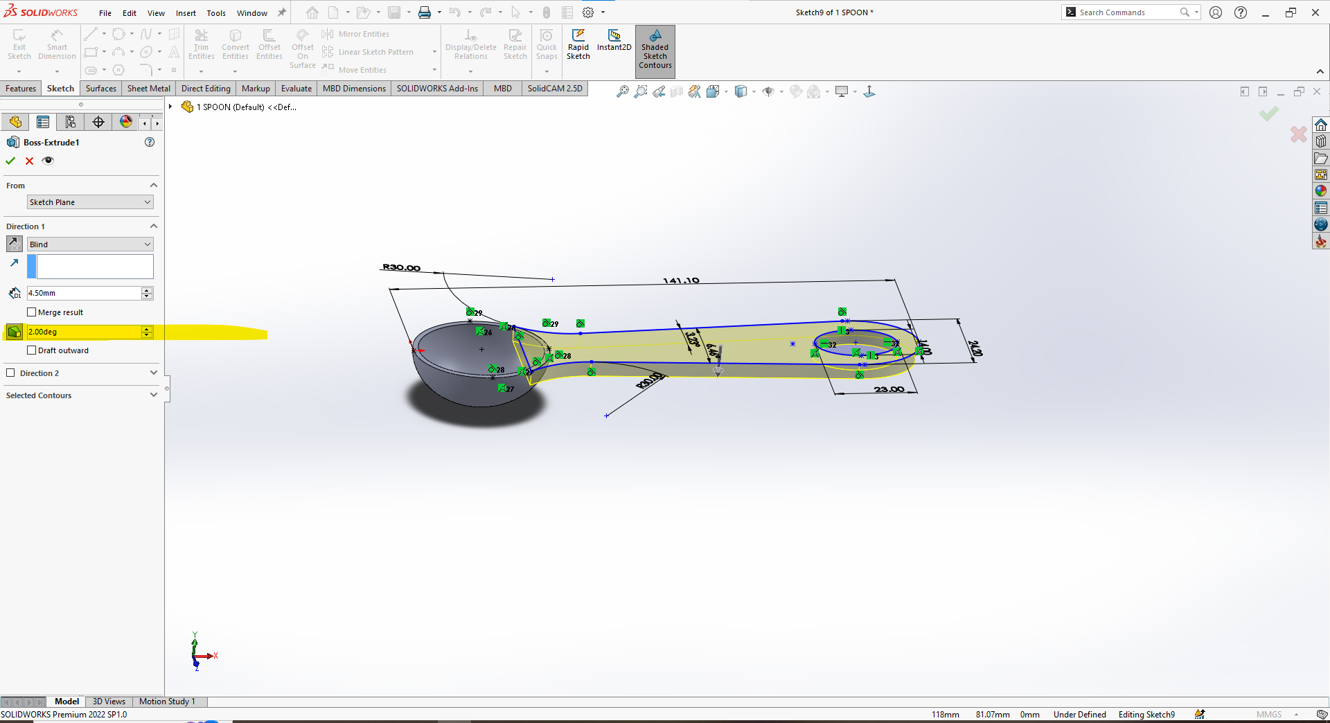
 

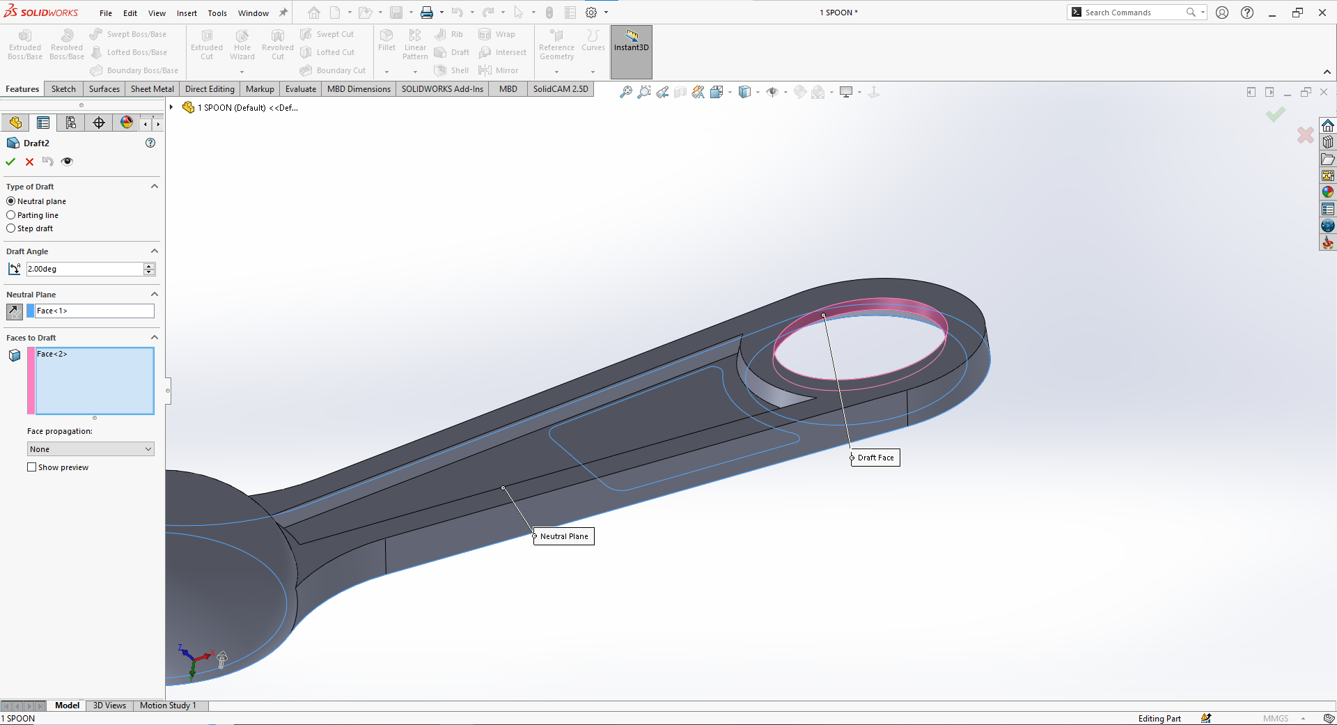
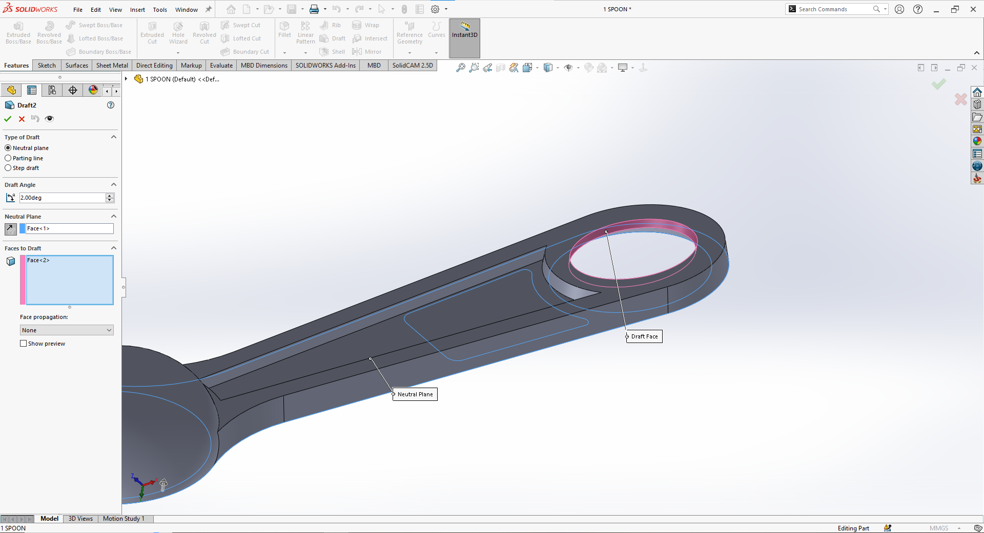
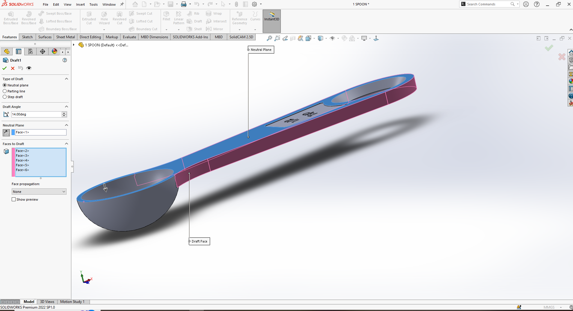
Draft Angles: In injection molding, a draft angle is the slight taper applied to vertical surfaces of a part to facilitate easy ejection from the mold. Without adequate draft, parts can stick, causing damage or requiring excessive ejection force. A typical draft angle ranges from 1° to 2° per side, but more may be needed for textured or deep parts. Proper draft improves mold longevity and ensures smooth part release, reducing defects and production delays. All faces perpendicular to the mold opening direction should have draft applied. Designing with draft in mind is essential for moldability, efficiency, and consistent part quality.
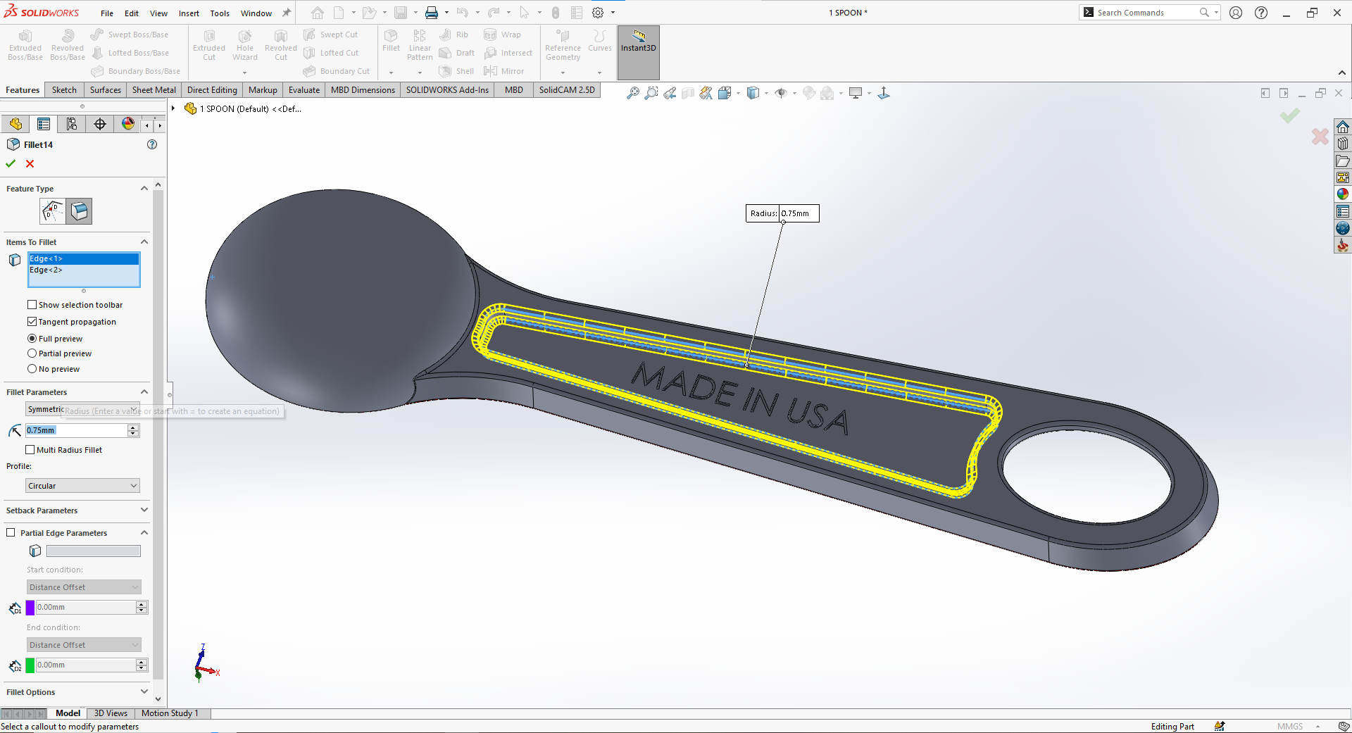
Radius and Fillets: In injection molding, radii and fillets are rounded transitions between surfaces that reduce stress concentrations, improve material flow, and enhance part strength. Sharp corners, especially internal ones, can cause weak points, warping, or incomplete filling. Adding fillets (internal curves) and radii (external curves) helps maintain uniform wall thickness and reduces wear on the mold. A good rule is to use an internal radius of at least 0.5× the wall thickness and match external radii accordingly. These smooth transitions also aid in ejection and overall part aesthetics. Proper use of fillets and radii is essential for durable, high-quality molded parts.
  1. Material Selection

Thermoplastics: Commonly used due to their re-meltable nature (e.g., PP, ABS, PC).

Thermosets: Used for high-temperature applications but are not reusable once set.

Additives: Include fillers, colorants, or reinforcements based on the desired properties.


  1. Tolerances

Dimensional Tolerance: Typically ±0.1mm to ±0.5mm, depending on the material and part size.

Surface Finish: Specify surface roughness (e.g., Ra 1.6 to Ra 12.5) based on the application.


  1. Ejection and Mold Release

Ejector Pins: Ejector pins are critical components in injection molding that push the finished part out of the mold once it has cooled and solidified. Located on the mold’s core side, they apply a controlled force to release the part without causing damage or deformation. Ejector pins are typically round and leave small, often visible marks on non-cosmetic surfaces. Proper pin placement is crucial to avoid warping or sticking, especially on large or thin-walled parts. Designers should provide flat, reinforced areas—called ejector pads—for pin contact. Effective ejection ensures consistent cycle times, part quality, and mold longevity in high-volume manufacturing.

Mold Release: Design features to minimize the need for mold release agents, such as textured surfaces or draft angles.

  1. Ribs and Bosses

Ribs: Ribs in injection molding are thin, protruding features used to reinforce plastic parts without adding excessive material or increasing wall thickness. They enhance structural rigidity, prevent bending, and support other features like bosses or mounting points. To avoid sink marks and warping, ribs should be designed with proper proportions: typically 50–70% of the adjacent wall thickness and no taller than three times that thickness. Draft angles of 0.5–1° and rounded bases help ensure smooth ejection and reduce stress concentrations. Well-designed ribs improve mechanical performance while maintaining moldability, ensuring strong, lightweight, and visually acceptable injection-molded components.

Bosses: Bosses in injection molding are raised cylindrical features typically used for assembly purposes, such as accommodating screws, inserts, or aligning parts. They should be designed with wall thickness no more than 60% of the adjoining wall to avoid sink marks and warping. Adding fillets at the base and reinforcing them with ribs or gussets enhances strength. Proper draft angles (typically 0.5–1°) help with ejection. Well-designed bosses improve part functionality, structural support, and manufacturability.

  1. Holes and Threads

Hole Diameter: In injection molding, hole diameter must be carefully designed to ensure moldability and part strength. Small holes can be difficult to mold accurately, while large holes may weaken the structure. A minimum diameter of 1 mm is recommended, depending on material and wall thickness. Holes should be placed with enough spacing from edges and other features to prevent stress concentration. For deep holes, core pins are used, and slight draft may be added to aid ejection and reduce wear.

Threads: In injection molding, thread diameter must be designed to ensure accurate molding and part strength. External threads are easier to mold than internal ones and should include a draft angle of 1–2° for smooth ejection. For internal threads, collapsible cores or unscrewing mechanisms may be required, increasing mold complexity. Threads should be coarse rather than fine to ensure proper filling and durability. The minimum recommended thread diameter is typically 5 mm, with sufficient clearance to avoid weak walls or distortion.


  1. Snap Fits and Assembly Features

Snap Fits: Design cantilever beams with adequate deflection (0.5mm to 2mm) and return angle (30° to 45°).

Assembly Features: Incorporate alignment features (e.g., guide pins, keyways) for ease of assembly.

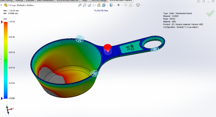
  1. Mold Flow and Fill Analysis

Flow Length-to-Thinness Ratio: Optimize the flow path to ensure even filling and minimize material pressure.

Weld Lines: Avoid placing critical features where weld lines may form, as they can weaken the part.

  1. Cooling and Shrinkage

Cooling Time: Ensure sufficient cooling time to prevent warping and dimensional inaccuracies.

Shrinkage: Account for material shrinkage (typically 0.1% to 2%) in your design.

  1. Aesthetics and Branding


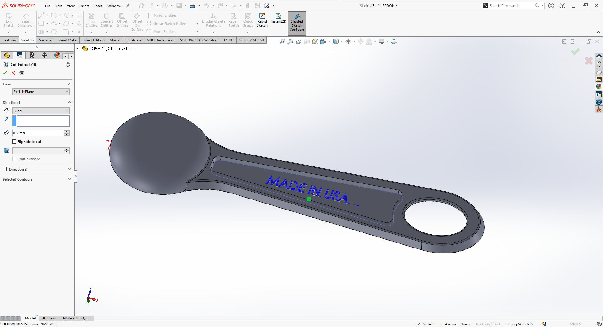
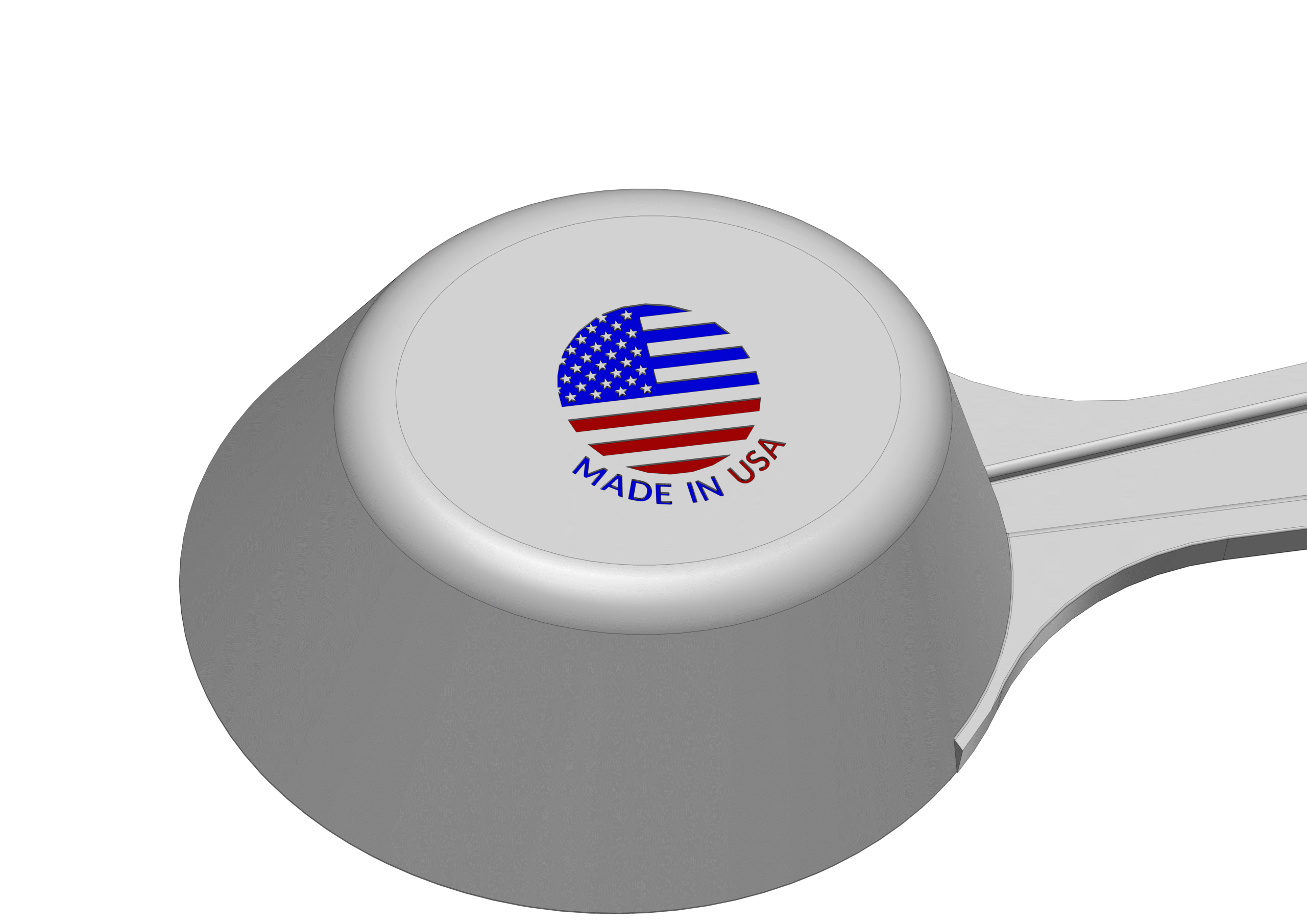
Logos and Markings: In injection molding, logo engraving should be designed with clear, moldable dimensions to ensure readability and ease of manufacturing. The minimum line width (diameter) for engraved features is typically 0.25 mm, depending on the material and mold precision. Engravings should not be too deep—usually 0.1 to 0.3 mm—to avoid sink marks and ensure smooth ejection. Placement on flat, non-critical surfaces is ideal. Adequate draft angles (at least 1°) help prevent damage during demolding and improve logo clarity.
  • Material Selection for Injection Molding

The choice of material is critical for the performance, cost, and manufacturability of your part.

  • Common Materials
  1. Polypropylene (PP): Lightweight, flexible, and chemical-resistant.
  2. Acrylonitrile Butadiene Styrene (ABS): Impact-resistant and suitable for high-temperature applications.
  3. Polycarbonate (PC): Transparent, impact-resistant, and suitable for optical applications.
  4. Polyethylene (PE): Low-cost, flexible, and chemical-resistant.
  5. Polyester (PET): High-strength, rigid, and suitable for packaging.
  • Material Properties to Consider

Mechanical Properties: Tensile strength, impact resistance, and flexural modulus.

Thermal Properties: Heat deflection temperature (HDT) and thermal conductivity.

Chemical Resistance: Compatibility with chemicals and cleaning agents.

Optical Properties: Transparency, gloss, and UV resistance.

  • Additives and Fillers

Reinforcements: Glass fibers for increased strength and stiffness.

Fillers: Minerals like calcium carbonate to reduce material costs.

Colorants: Pigments or masterbatches for custom colors.

UV Stabilizers: To prevent degradation from UV exposure.

  • Sustainability Considerations

Recyclability: Choose materials that are recyclable or biodegradable.

Bioplastics: Consider PLA (Polylactic Acid) or PHA (Polyhydroxyalkanoates) for eco-friendly applications.

Material Efficiency: Optimize part weight and thickness to minimize material usage.

  • Design for Manufacturability (DFM)

Design for Manufacturability (DFM) is a critical aspect of injection molding that ensures your part can be produced efficiently and cost-effectively.

  • Key DFM Principles
  1. Simplify the Design: Avoid unnecessary complexity that could increase tooling costs or lead to manufacturing defects.
  2. Minimize Undercuts: Undercuts require side actions in the mold, which increase tooling complexity and cost.
  3. Avoid Thin Walls: Ensure wall thickness is consistent and within recommended limits to prevent warping and sink marks.
  4. Use Standard Features: Standardize features like bosses, ribs, and snaps to reduce design variability.
  • Moldability Analysis

Flow Analysis: Use simulation tools to analyze how molten plastic flows into the mold cavity.

Pressure Drop: Ensure that the pressure drop is within acceptable limits to avoid material degradation.

Cooling Analysis: Optimize cooling channels to ensure uniform cooling and minimize warping.

  • Design for Assembly (DFA)

Snap Fits: Use snap fits to eliminate the need for fasteners.

Alignment Features: Incorporate guide pins, keyways, or chamfers to facilitate easy assembly.

Modular Design: Design parts that can be easily assembled into a complete product.

  • Cost Reduction Strategies

Reduce Material Usage: Optimize part weight and thickness to minimize material costs.

Simplify Tooling: Avoid complex mold features that increase tooling costs.

Increase Production Volume: Take advantage of economies of scale by producing larger batches.

  • Tooling and Mold Design

The mold is a critical component of the injection molding process, and its design directly impacts the quality, cost, and lead time of your part.

  • Key Components of a Mold
  1. Cavity: The part of the mold that shapes the plastic into the desired form.
  2. Core: The part of the mold that creates holes or recesses in the part.
  3. Runner System: Channels that direct molten plastic from the injection unit to the mold cavity.
  4. Gates: Points where molten plastic enters the mold cavity.
  5. Ejector Pins: Mechanisms that push the part out of the mold after cooling.


  • Mold Types
  1. Single-Cavity Mold: Produces one part per cycle. Ideal for low-volume production.
  2. Multi-Cavity Mold: Produces multiple parts per cycle. Ideal for high-volume production.
  3. Family Mold: Produces multiple parts of similar size or shape. Reduces tooling costs.
  4. Hot Runner Mold: Uses insulated runners to keep the plastic molten between shots. Reduces material waste.


  • Mold Materials
  1. Steel: Most common mold material due to its durability and cost-effectiveness.
  2. Aluminum: Used for prototype molds or low-volume production due to its faster machining time.
  3. Beryllium Copper: Used for high-wear areas due to its high thermal conductivity.


  • Mold Surface Finish

Polishing: Improves part quality and reduces mold wear.

Texturing: Creates surface textures for aesthetic or functional purposes.

Coating: Applies wear-resistant or corrosion-resistant coatings to critical areas.


  • Mold Maintenance

Cleaning: Regularly clean the mold to prevent contamination and material buildup.

Lubrication: Lubricate moving parts to reduce wear and tear.

Inspection: Inspect the mold for damage or wear and perform repairs as needed.


  • Surface Finishing and Textures

Surface finishing and textures play a crucial role in the aesthetics and functionality of injection-molded parts.


  • Common Surface Finishes
  1. Polished Finish: Achieved by polishing the mold cavity to a high gloss. Ideal for optical applications.
  2. Textured Finish: Creates a specific surface texture for grip, aesthetics, or functionality.
  3. Matte Finish: Provides a dull, non-reflective surface. Ideal for hiding mold marks or imperfections.
  4. Etched Finish: Creates a fine, detailed texture using chemical etching.


  • Texture Patterns
  1. Fine Texture: Provides a smooth, low-gloss surface.
  2. Medium Texture: Offers a balanced combination of aesthetics and functionality.
  3. Coarse Texture: Ideal for applications requiring high grip or durability.


  • Functional Textures

Grip Textures: Used on handles, grips, and other areas requiring traction.

Ventilation Textures: Create airflow or drainage in applications like filters or vents.

Aesthetic Textures: Enhance the visual appeal of the part.


  • Application Methods
  1. Mold Texturing: Textures are incorporated directly into the mold cavity.
  2. Post-Molding Texturing: Textures are applied after molding using processes like laser etching or pad printing.
  3. Insert Molding: Textures are molded into inserts that are then assembled into the final part.


  • Assembly and Post-Molding Operations

Many injection-molded parts require additional assembly or post-molding operations to meet their functional requirements.


  • Assembly Methods
  1. Snap Fits: Use cantilever beams or other snap-fit features to eliminate the need for fasteners.
  2. Ultrasonic Welding: Join parts using high-frequency vibrations to create a strong bond.
  3. Adhesive Bonding: Use adhesives to join parts, especially when different materials are involved.
  4. Screw or Rivet Assembly: Use mechanical fasteners for applications requiring high strength or adjustability.


  • Post-Molding Operations
  1. Printing: Apply labels, logos, or other graphics using screen printing, pad printing, or laser marking.
  2. Painting: Apply paint for aesthetic or functional purposes, such as color matching or UV resistance.
  3. Plating: Apply metal coatings for conductivity, corrosion resistance, or aesthetics.
  4. Machining: Perform secondary machining operations like drilling, tapping, or grinding for precision features.


  • Automation in Assembly

Robotic Assembly: Use robots to automate repetitive tasks like screw driving or welding.

Vision Systems: Use vision systems to inspect and guide assembly operations.

Conveyor Systems: Use conveyor systems to move parts through the assembly line efficiently.


  • Design for Assembly (DFA)

Simplify the Design: Minimize the number of parts and fasteners to reduce assembly time and cost.

Modular Design: Design parts that can be easily assembled into a complete product.

Alignment Features: Incorporate guide pins, keyways, or chamfers to facilitate easy alignment during assembly.


  • Testing and Validation

Before moving to mass production, it’s essential to test and validate your design to ensure it meets the required performance, safety, and quality standards.


  • Types of Testing
  1. Mechanical Testing: Evaluate the part’s strength, stiffness, and impact resistance.
  2. Thermal Testing: Test the part’s performance under extreme temperatures.
  3. Chemical Resistance Testing: Assess the part’s resistance to chemicals and cleaning agents.
  4. Optical Testing: Evaluate the part’s clarity, gloss, and UV resistance.
  5. Functional Testing: Test the part’s functionality in its intended application.


Rapid Prototyping: Use 3D printing or CNC machining to create prototypes for testing.

Design Iteratio: Refine the design based on test results and feedback.

Design Freeze: Finalize the design once all issues have been resolved.


  • Quality Control

Inspection: Regularly inspect parts for defects or variations.

Dimensional Measurement: Measure critical dimensions to ensure compliance with specifications.

Statistical Process Control (SPC): Monitor the production process to maintain consistent quality.


As environmental concerns grow, designing sustainable injection-molded parts is becoming increasingly important.


  • Key Sustainability Considerations
  1. Material Selection: Choose materials that are recyclable, biodegradable, or made from renewable resources.
  2. Material Efficiency: Optimize part weight and thickness to minimize material usage.
  3. Energy Efficiency: Design parts that can be produced using less energy and water.
  4. End-of-Life Design: Design parts for disassembly, recycling, or biodegradation.


  • Bioplastics

PLA (Polylactic Acid): A biodegradable thermoplastic made from renewable resources like corn starch or sugarcane.

PHA (Polyhydroxyalkanoates): A biodegradable thermoplastic produced from bacterial fermentation.

PBAT (Polybutylene Adipate-co-Butylene Terephthalate): A biodegradable thermoplastic used for flexible applications.


  • Recyclable Materials

Recycled Plastics: Use post-consumer recycled (PCR) or post-industrial recycled (PIR) materials.

Material Identification: Use material identification codes to facilitate sorting and recycling.


  • Design for Recyclability

Simplify the Design: Avoid complex geometries or multiple materials that complicate recycling.

Material Separation: Design parts that can be easily disassembled and separated into different materials.

Avoid Contaminants: Minimize the use of additives, coatings, or adhesives that can contaminate recycled materials.


  • Cost Considerations and Optimization

Understanding the cost drivers in injection molding is essential for optimizing your design and reducing production expenses.


  • Key Cost Drivers
  1. Tooling Costs: The cost of designing and building the mold is a significant upfront expense.
  2. Material Costs: The cost of the plastic material used to produce the part.
  3. Production Volume: Higher production volumes reduce the per-unit cost due to economies of scale.
  4. Complexity: Complex geometries, undercuts, and multiple cavities increase tooling and production costs.


  • Cost Reduction Strategies
  1. Simplify the Design: Avoid unnecessary complexity that increases tooling and production costs.
  2. Use Standard Features: Standardize features like bosses, ribs, and snaps to reduce design variability.
  3. Optimize Material Usage: Minimize material waste by optimizing part weight and thickness.
  4. Use Recycled Materials: Incorporate recycled plastics to reduce material costs.
  5. Increase Production Volume: Take advantage of economies of scale by producing larger batches.


  • Total Cost of Ownership (TCO)

Material Costs: The cost of the plastic material over the product’s lifecycle.

Tooling Costs: The upfront cost of designing and building the mold.

Production Costs: The cost of producing the part, including labor, energy, and overhead.

Post-Molding Costs: The cost of additional operations like assembly, painting, or packaging.

Warranty and Repair Costs: The cost of repairing or replacing defective parts.


  • Case Studies and Examples

Real-world examples provide valuable insights into the challenges and opportunities of designing parts for injection molding.


  • Case Study 1: Consumer Electronics Housing

Challenge: Design a lightweight, impact-resistant housing for a portable electronic device.

Solution: Use ABS for its high impact resistance and process ability. Incorporate ribs and gussets for added stiffness without increasing material usage.

Outcome: A durable, cost-effective housing that meets the required performance and aesthetic standards.


  • Case Study 2: Medical Device Component

Challenge: Design a clear, autoclavable component for a medical device.

Solution: Use PC for its transparency and high heat resistance. Incorporate textured surfaces for grip and alignment features for easy assembly.

Outcome: A component that meets strict medical standards for clarity, sterility, and functionality.


  • Case Study 3: Automotive Part

Challenge: Design a lightweight, heat-resistant part for an automotive application.

Solution: Use a glass-filled PA6 for its high strength, stiffness, and heat resistance. Optimize the design for minimal material usage and easy assembly.

Outcome: A cost-effective, high-performance part that meets the demanding requirements of the automotive industry.


  • Best Practices and Future Trends

Adhering to best practices and staying informed about future trends ensures that your designs remain competitive and innovative.


  • Best Practices
  1. Collaborate with Mold Makers: Work closely with mold makers to ensure your design is manufacturable.
  2. Use Simulation Tools: Utilize mold flow and structural analysis tools to optimize your design.
  3. Consider Sustainability: Design parts with sustainability in mind, using recyclable or biodegradable materials.
  4. Iterate and Refine: Continuously refine your design based on testing and feedback.


  • Future Trends
  1. Advanced Materials: Development of new materials with enhanced properties, such as self-healing plastics.
  2. Digital Manufacturing: Increased use of digital tools for design, simulation, and production.
  3. Circular Economy: Focus on designing parts for recyclability, reusability, and biodegradability.
  4. Additive Manufacturing: Integration of additive manufacturing techniques with injection molding for hybrid production methods.

By following the insights and guidelines outlined in this guide, you can design injection-molded parts that are functional, cost-effective, and sustainable. Whether you’re a seasoned designer or just starting out, understanding the principles of injection molding will empower you to create innovative solutions that meet the demands of modern manufacturing.

Key Takeaways from the IVT Expo: Advancing Off-Highway Technology

The IVT Expo in Chicago was a showcase of the latest advancements in off-highway vehicle technology, providing critical insights into the future of the industry. A strong emphasis was placed on electrification, with several industry leaders unveiling new powertrain solutions aimed at improving efficiency and reducing emissions. The development of advanced controls and sensor systems was also a highlight, with innovations that promise to enhance the precision and reliability of off-highway vehicles in challenging environments.

Electrification and Sustainability

The trend towards electrification is reshaping the off-highway sector, with companies like Bosch Rexroth and John Deere Electronics presenting solutions that push the boundaries of what’s possible with electric and hybrid powertrains. These innovations are not just about reducing emissions but also about delivering the performance and durability needed for heavy-duty applications.

Advanced Controls and Automation

The expo also underscored the importance of advanced controls and automation. Exhibitors like Husco and Epec Oy showcased the latest in joystick controls, integrated sensor systems, and automation technologies. These systems are designed to improve operator experience, increase machine precision, and ensure that vehicles can handle the most demanding tasks with greater efficiency and safety.

Camera Systems and Safety Enhancements

Safety remains a top priority in the off-highway sector, and the IVT Expo did not disappoint with its focus on camera systems and safety enhancements. Companies such as SPAL Automotive USA and Multi-Wing America Inc. introduced new camera technologies that enhance visibility and operational safety, particularly in complex working environments where visibility is crucial.

System Integration and Supply Chain Optimization

Integration and seamless technology adoption were other key themes at the expo. Leading companies like Bonfiglioli USA and Schafer Driveline presented comprehensive system integration solutions that are designed to simplify the adoption of new technologies while optimizing supply chains. These integrators are helping the industry move towards more streamlined operations, ensuring that new advancements can be integrated quickly and effectively.

Conclusion

The IVT Expo highlighted the rapidly evolving landscape of off-highway vehicle technology. From electrification and advanced controls to enhanced safety systems and supply chain integration, the innovations presented at the show are set to drive the industry forward. Staying updated on these developments is crucial for anyone involved in off-highway technology, as the tools and systems showcased here will define the next generation of vehicles and machinery.

For further information on the latest innovations and to stay informed about upcoming advancements in injection molding solutions, custom thermoformed plastics, and fiberglass products manufacturers, and  visit the omrajtech website.

6 Strategies to Reduce Cost of Plastic Parts in Injection Molding

As a sourcing or purchasing manager, reducing costs while maintaining quality is one of your top priorities. When it comes to plastic injection molding, there are several strategies you can use to cut down expenses without sacrificing the performance of your plastic parts. Here are six practical ways to optimize costs in your plastic injection molding projects:

Key Cost Reduction Strategies:

  • Choose the Right Material: Opt for materials that offer the best balance between cost and performance.

  • Simplify the Design: Work with your design team to remove complex features that drive up production costs.

  • Improve Process Efficiency: Make small adjustments to the production process to increase output without additional resources.

  • Reduce Waste: Implement better material management to minimize waste and maximize material usage.

  • Work Closely with Suppliers: Negotiate better pricing and collaborate on cost-effective solutions.

  • Focus on Continuous Improvement: Regularly review and refine processes to keep reducing costs over time.

1. Choose the Right Material

Selecting the right material can make a big difference in your costs. For example, if you’re currently using a high-performance plastic that costs $10 per kilogram, consider whether a similar material that costs $8 per kilogram could do the job just as well. By switching to the less expensive material, you could reduce your material costs by 20%, all without compromising the quality of your parts.

This simple step can help you achieve significant savings, especially in large production runs.

Plastic Resin Price Index (paid subscription needed) : Plastic News Resin Prices North America

You may find the newsletter from Cody Bates useful for costing resins for your products.

2. Simplify the Design

The design of your plastic parts plays a huge role in the overall cost. For instance, if your part has a complex feature like an undercut that requires special tooling, it’s going to be more expensive to produce. By working with your design team to simplify the part—say, by removing the undercut—you could save thousands of dollars in tooling costs and make the production process faster and more efficient.

Simpler designs not only lower costs but also speed up production, allowing you to meet tight deadlines and reduce labor expenses.

3. Improve Process Efficiency

Improving how the injection molding process is carried out can also lead to cost savings. For example, if you can reduce the cooling time by just a few seconds per cycle, you can produce more parts in the same amount of time. Let’s say you currently produce 1,000 parts per day with a cycle time of 60 seconds. Cutting the cycle time by 5 seconds could boost your output by an additional 100 parts per day.

This means you’re getting more parts without spending more money on extra resources, effectively reducing your per-unit cost.

4. Reduce Waste

Waste during production is money lost. If you’re seeing a waste rate of 10% in your material usage, there’s room for improvement. By implementing better material management practices, optimizing the runner and gating systems, and reusing scrap material, you could cut your waste rate in half. For example, reducing waste from 10% to 5% in a production run that uses 1,000 kilograms of material per month could save you 50 kilograms of material.

Less waste means direct savings, which adds up over time, especially in high-volume production.

5. Work Closely with Suppliers

Building strong relationships with your suppliers can lead to cost reductions as well. For instance, negotiating better pricing or bulk purchase discounts on materials can help you save significantly. If your annual material cost is $500,000, even a small 5% discount could save you $25,000. Additionally, collaborating with tooling suppliers to find cost-effective solutions can lower your upfront costs and reduce maintenance expenses down the line.

Good supplier relationships are key to securing the best deals and finding cost-effective solutions that meet your needs.

6. Focus on Continuous Improvement

Continuous improvement isn’t just a buzzword—it’s a way to keep costs down over time. By regularly reviewing and refining your processes, you can identify areas where efficiency can be improved. For example, setting up a team to focus on process improvements could help you reduce overall manufacturing costs by 10%.

Ongoing efforts to streamline production will keep you ahead of the competition and help you meet your cost reduction targets year after year.

Conclusion

Reducing costs in plastic injection molding doesn’t have to mean compromising on quality. By focusing on smart material choices, simplified designs, process efficiency, waste reduction, supplier collaboration, and continuous improvement, you can achieve significant savings. As a sourcing or purchasing manager, these strategies will help you meet your cost targets, making your projects more profitable and your company more competitive.

Top 5 Low-Volume and Prototyping Thermoforming Suppliers in the USA

For businesses looking to produce custom thermoformed parts in low volumes or create prototypes before committing to large-scale production, finding the right thermoforming supplier is crucial. Low-volume thermoforming services allow companies to validate designs, explore different material options, and ensure that their products meet specific requirements without the cost and commitment of full-scale production. Here are the top 5 low-volume and prototyping thermoforming suppliers in the USA, offering tailored solutions for your manufacturing needs.

Top 5 Low-Volume and Prototyping Thermoforming Suppliers:

  1. Xometry

  2. STM Plastics (represented by Om Raj Tech)

  3. Protolabs

  4. Universal Plastics

  5. Allied Plastics

1. Xometry

Overview:
Xometry is a leading on-demand manufacturing platform with a vast network of suppliers. They provide low-volume and prototyping thermoforming services, offering flexible production options for clients across various industries.

Key Benefits:

  • Fast turnaround times for prototypes and small runs.

  • Access to a wide variety of thermoplastics.

  • Nationwide network of vetted manufacturers.

Pros:

  • Extensive material options and fast lead times.

  • Ideal for rapid prototyping and low-volume production.

  • User-friendly online platform for instant quotes.

Cons:

  • Limited customization for highly specialized applications.

2. STM Plastics (Represented by Om Raj Tech)

Overview:
STM Plastics, based in Augusta, Kansas, is known for its specialization in custom low-volume thermoforming services. With a focus on prototyping and short production runs, STM Plastics offers personalized engineering support and tailored solutions to meet specific client needs.

Key Benefits:

  • Dedicated support for small-run thermoforming projects.

  • Experienced in heavy-gauge and thin-gauge thermoforming.

  • Emphasis on high-quality prototyping.

Pros:

  • Custom design assistance and rapid prototyping capabilities.

  • Excellent customer service with attention to detail.

  • Flexible production capabilities for low-volume orders.

Cons:

  • Smaller operation may limit large-scale production capacity.

Contact Us to get a quick quote on your prototyping need.

3. Protolabs

Overview:
Protolabs is renowned for its digital manufacturing services, offering fast and affordable low-volume thermoforming and prototyping solutions. Their advanced automation helps reduce lead times while maintaining high precision in product design and quality.

Key Benefits:

  • Fast quotes and efficient prototyping services.

  • Advanced thermoplastic material options.

  • Emphasis on digital and automated production processes.

Pros:

  • Speedy prototyping services with short lead times.

  • Suitable for clients needing precise, small-batch thermoformed parts.

  • Wide array of material choices.

Cons:

  • Higher costs for highly customized projects.

4. Universal Plastics

Overview:
With decades of experience, Universal Plastics offers custom low-volume thermoforming services, focusing on both prototyping and short production runs. They provide solutions for industries such as aerospace, medical, and consumer goods.

Key Benefits:

  • Custom tooling and prototyping services.

  • Expertise in thin-gauge and heavy-gauge thermoforming.

  • A focus on delivering high-quality prototypes for testing and validation.

Pros:

  • Strong experience in complex thermoformed parts.

  • In-house design and engineering support.

  • High attention to detail and quality assurance.

Cons:

  • Lead times may be longer for custom projects compared to smaller, more agile suppliers.

5. Allied Plastics

Overview:
Allied Plastics offers thermoforming services for prototyping and small production runs. Their focus on quality, design flexibility, and customer satisfaction makes them an excellent choice for clients in need of custom low-volume parts.

Key Benefits:

  • Custom design services for small-batch projects.

  • Expertise in prototyping and small production runs.

  • Focus on maintaining cost-effective solutions for clients.

Pros:

  • Strong design flexibility for various industries.

  • Quality assurance with thorough testing protocols.

  • Competitive pricing for low-volume production.

Cons:

  • Less automation compared to larger competitors, which may lead to longer production times.

Conclusion

When selecting a low-volume or prototyping thermoforming supplier, it’s essential to consider factors like turnaround time, material availability, and design flexibility. STM Plastics, represented by Om Raj Tech, stands out for its exceptional customer service and flexible, custom solutions for prototyping and low-volume production. Whether you’re creating prototypes for validation or need small-scale manufacturing, the suppliers listed above offer the expertise and capabilities to bring your designs to life.

For more information about how Om Raj Tech and STM Plastics can support your low-volume thermoforming needs, contact us today!

Top 5 Thermoforming Suppliers for Full Production in the USA

When it comes to full-scale thermoforming production, selecting the right supplier is critical to ensure high-volume manufacturing while maintaining quality and efficiency. Whether you’re producing parts for automotive, agriculture, medical, or consumer goods, a reliable thermoforming supplier with experience in full production can make all the difference. Here are the top 5 thermoforming suppliers in the USA that offer exceptional capabilities for large-scale manufacturing.

Top 5 Thermoforming Suppliers for Full Production in the USA (Alphabetical Order):

  1. Advanced Plastiform, Inc.

  2. Placon

  3. STM Plastics (represented by Om Raj Tech)

  4. Tekni-Plex

  5. Universal Plastics

1. Advanced Plastiform, Inc.

Overview:
Advanced Plastiform, Inc. (API) is a trusted supplier of full-scale thermoforming services, offering solutions for industries such as automotive, agriculture, and industrial equipment. API provides heavy-gauge thermoforming and complex part manufacturing, ensuring durability and precision for large-scale applications.

Key Benefits:

  • Expertise in heavy-gauge thermoforming for durable, large-scale parts.

  • Custom design services for complex projects in automotive and agriculture.

  • Strong focus on quality control and consistent production.

Pros:

  • Extensive experience with heavy-gauge parts for industrial applications.

  • Full-scale production capabilities with advanced design support.

  • Ability to handle complex and oversized parts.

Cons:

  • Focused on heavy-gauge thermoforming, limiting thin-gauge options.

2. Placon

Overview:
Placon is one of the leading thermoforming suppliers in the USA, known for its full production capabilities across a wide range of industries including food packaging, healthcare, and consumer goods. Placon has decades of experience in high-volume production, offering innovative thermoformed packaging solutions with a focus on sustainability and quality.

Key Benefits:

  • Full production capabilities for large-scale orders.

  • Focus on sustainable materials and eco-friendly solutions.

  • Advanced design and engineering support for complex projects.

Pros:

  • Extensive experience in the packaging industry.

  • Large production capacity to meet high-volume demands.

  • Focus on sustainability and reducing environmental impact.

Cons:

  • Primarily focused on the packaging sector, limiting versatility in other industries.

3. STM Plastics (Represented by Om Raj Tech)

Overview:
STM Plastics, based in Augusta, Kansas, offers full production thermoforming services with a focus on custom solutions for agriculture, automotive, and medical industries. STM Plastics specializes in both thin-gauge and heavy-gauge thermoforming, delivering high-quality, durable parts for large-scale production. Their personalized approach and flexibility make them an ideal partner for full production projects.

Key Benefits:

  • Full production capabilities for both thin and heavy-gauge thermoforming.

  • Custom solutions tailored to client-specific needs across various industries.

  • Strong focus on quality control and customer satisfaction.

Pros:

  • Excellent customer service with a focus on full production.

  • Flexibility to handle both small and large production runs.

  • Experienced in serving the automotive, agriculture, and medical industries.

Cons:

  • STM Plastics’ operation size allows them to provide more personalized service, making them an ideal partner for clients seeking tailored attention to their projects.

Contact Us

4. Tekni-Plex

Overview:
Tekni-Plex is a global leader in thermoforming and polymer solutions, offering full production capabilities for the medical, pharmaceutical, and food packaging industries. With their state-of-the-art facilities, Tekni-Plex delivers consistent high-quality products while adhering to strict industry standards and regulations.

Key Benefits:

  • Expertise in medical, pharmaceutical, and food packaging industries.

  • Advanced thermoforming technology and automation for high-volume production.

  • Strong focus on regulatory compliance and quality assurance.

Pros:

  • ISO and FDA-certified facilities ensuring top-notch quality and safety.

  • Extensive experience in full-scale thermoforming production.

  • Strong commitment to innovation and technology.

Cons:

  • Primarily focused on highly regulated industries, limiting flexibility for general manufacturing.

5. Universal Plastics

Overview:
Universal Plastics is a well-known full-service thermoforming supplier, offering production capabilities for a wide range of industries including medical, aerospace, and consumer products. Universal Plastics specializes in both thin-gauge and heavy-gauge thermoforming, providing full production services from prototyping to final manufacturing.

Key Benefits:

  • Full-scale production capabilities for both thin and heavy-gauge projects.

  • Serves diverse industries such as medical, aerospace, and consumer goods.

  • Strong design and engineering support throughout the production process.

Pros:

  • Versatile production capabilities across multiple industries.

  • Expertise in both small and large-scale thermoforming projects.

  • Dedicated design and prototyping services to ensure high-quality production.

Cons:

  • Longer lead times for highly complex projects.

Conclusion

Choosing the right thermoforming supplier for full production requires careful consideration of their capabilities, industry experience, and ability to scale. STM Plastics, represented by Om Raj Tech, stands out for its customer-focused approach, full production capabilities, and expertise across multiple industries. Whether you’re looking for high-volume packaging or durable automotive parts, these top 5 suppliers provide the experience and reliability to meet your thermoforming needs.

For more information on how Om Raj Tech and STM Plastics can support your full production thermoforming projects, contact us today!

Reducing Return Rates for Thermoformed Plastic Parts: Technical Solutions for Better Quality

Thermoforming is a versatile process used to create plastic components, often for large-scale applications in industries like automotive, packaging, and medical devices. However, when the return rate of thermoformed parts increases, it indicates underlying issues related to material handling, tooling, or process control. In this article, we will explore the most common causes of product returns for thermoformed plastic parts and discuss technical solutions that can improve quality, reduce defects, and optimize production.

1. Common Issues Leading to Thermoformed Plastic Part Returns

Thermoformed parts can suffer from defects due to improper material handling, poor tooling design, or inconsistent process control. Addressing these issues at their root is critical to reducing returns and improving product quality.

1.1. Inconsistent Thickness

One of the most frequent causes of part returns in thermoforming is inconsistent material thickness. Thin or thick spots can weaken the part or lead to aesthetic issues, especially for consumer-facing products or those requiring structural integrity.

  • Uneven Heating: If the plastic sheet is not heated evenly before forming, the material may not stretch uniformly, resulting in sections that are too thin or too thick.

  • Improper Tool Design: Molds that don’t properly account for material distribution during the forming process can also contribute to uneven thickness.

Solution: Optimize heating control through precise temperature monitoring. Suppliers should use infrared temperature sensors and zoned heaters to ensure even heating of the plastic sheet before forming. Additionally, tool design must take material flow and thickness into account by using DFM (Design for Manufacturability) principles to create uniform part distribution.

1.2. Surface Defects

Surface defects in thermoformed parts, such as bubbles, pitting, or rough textures, can lead to aesthetic rejections or functional failures, especially in parts used for packaging or medical applications.

  • Bubbles or Voids: These are often caused by trapped air during the forming process or by improperly dried materials.

  • Surface Roughness or Pitting: Uneven mold surfaces, poor material selection, or improper cooling can result in rough or pitted surfaces on the final part.

Solution: To prevent bubbles, ensure that plastic sheets are dried correctly before the thermoforming process. Use automated material dryers to control moisture content and prevent contamination. For surface defects, regular mold maintenance is essential, ensuring that molds are kept clean and polished. Cooling cycles should also be carefully controlled to prevent surface pitting or roughness, especially for parts requiring a high-quality finish.

1.3. Warping

Warping occurs when the plastic part cools unevenly, leading to a distorted shape. This is a common issue in large thermoformed parts and can result in poor fit or functional failure.

  • Improper Cooling: Uneven cooling across the part can lead to warping as different sections contract at different rates.

  • Tooling Issues: Inadequate venting or poor tool design can exacerbate warping by restricting airflow or causing uneven pressure distribution during forming.

Solution: Implement controlled cooling systems to ensure uniform temperature across the part during the cooling phase. Adding strategically placed vents to the mold can improve air circulation and prevent uneven cooling. Additionally, suppliers should use simulation tools to model airflow and temperature gradients, enabling them to adjust tooling and process parameters accordingly.

2. Technical Solutions for Reducing Thermoformed Plastic Part Defects

The key to reducing return rates and improving the quality of thermoformed plastic parts lies in addressing the specific technical challenges associated with material handling, tooling design, and process control. Below are some advanced solutions that can be implemented.

2.1. Vacuum and Pressure Forming Optimization

Thermoforming involves either vacuum forming (for thin-gauge parts) or pressure forming (for thicker, more detailed parts). Both processes require precise control of pressure, temperature, and material flow to prevent defects.

  • Vacuum Forming: If vacuum pressure is too low or uneven, parts may not adhere fully to the mold, leading to thin areas or incomplete forms.

  • Pressure Forming: Pressure forming requires more force to push the material into detailed molds. Poor pressure control can result in uneven thickness or poor surface detail.

Solution: Use vacuum and pressure control systems with fine-tuning capabilities to ensure uniform distribution of pressure across the material. Automated pressure systems can dynamically adjust based on the part’s requirements, ensuring consistent thickness and detailed surface finishes. Additionally, perform flow analysis simulations to determine the best vacuum and pressure settings for each design.

2.2. Tooling and Mold Design

The quality of the mold used in thermoforming directly impacts the part’s thickness distribution, surface finish, and dimensional accuracy. Poorly designed molds can cause defects like warping, uneven material distribution, or incomplete forming.

  • Poor Mold Venting: Insufficient venting can cause trapped air, leading to bubbles or uneven material distribution.

  • Inadequate Mold Maintenance: Over time, molds can wear out, leading to surface defects or inconsistent part quality.

Solution: Proper mold design with adequate venting channels ensures that air is evacuated efficiently during the forming process, preventing trapped air or uneven stretching of the material. Tool maintenance programs should be implemented to inspect and polish molds regularly, ensuring consistent surface quality and part performance. For more complex parts, use aluminum prototype tooling for low-volume runs to validate the mold design before moving to full-scale production.

2.3. Temperature Control and Material Handling

Proper material handling and temperature control are essential for producing high-quality thermoformed parts. Variations in material temperature can lead to defects like warping, bubbles, or poor surface finish, while improper material handling can introduce contamination.

  • Uneven Material Heating: If different areas of the plastic sheet are heated to different temperatures, the material may stretch unevenly, causing inconsistent thickness or warping.

  • Material Contamination: Dust or moisture can affect material properties, leading to poor adhesion or surface defects.

Solution: Implement zoned heating systems to ensure that all areas of the material are heated evenly. This is especially important for complex parts that require uniform thickness and intricate details. In addition, use automated material dryers to remove moisture from plastic sheets and prevent contamination. Regular material audits should be conducted to ensure consistency in material quality.

3. Monitoring Quality and Reducing Returns

Thermoforming manufacturers can significantly reduce return rates by adopting automated quality control systems and collecting real-time production data. These technologies allow for early detection of defects and process improvements before defective parts are shipped.

3.1. In-Process Inspection

Automated vision inspection systems can monitor parts as they come off the production line, ensuring that they meet thickness, surface quality, and dimensional requirements. These systems reduce the number of defective parts by identifying and isolating issues before they result in returns.

  • Laser Thickness Gauging: This tool measures the thickness of the part in real-time, ensuring consistency across the product.

  • Surface Scanning: Automated surface scanning technology can detect surface defects like pitting, roughness, or bubbles, ensuring that parts meet aesthetic and functional requirements.

3.2. Data-Driven Process Control

By collecting data from each production run, manufacturers can track trends, identify recurring issues, and implement proactive solutions to reduce defects.

  • Process Monitoring Systems: Real-time monitoring of critical process parameters (e.g., temperature, pressure, cooling time) enables manufacturers to make adjustments as soon as deviations occur. This minimizes the number of defective parts and reduces scrap.

  • Trend Analysis and Continuous Improvement: By analyzing production data, manufacturers can identify patterns and recurring issues, helping them adjust processes or tooling to improve part quality over time.

Conclusion

Reducing return rates for thermoformed plastic parts requires careful attention to material handling, tooling design, and process control. By implementing advanced technical solutions like vacuum/pressure control, optimized tool design, and automated quality inspection systems, manufacturers can significantly improve part quality and reduce product returns.

Om Raj Tech – Your Partner in Thermoforming Excellence

At Om Raj Tech, we partner with industry-leading thermoforming manufacturers to deliver high-quality, reliable plastic parts. Our partners use advanced temperature control, optimized tooling, and real-time quality monitoring to ensure consistent part quality. Contact us today to explore how we can optimize your thermoforming process and reduce product returns.

Designing Thermoformed Plastic Safety Covers for Machines: Compliance with OSHA Standards for Moving Parts

In industrial and manufacturing settings, machines with moving components such as motors, bearings, shafts, belts, and pulleys pose significant safety risks if left exposed. Safety covers designed with thermoformed plastic can effectively protect workers from these hazards while adhering to OSHA standards, particularly 29 CFR Part 1910, which specifies requirements for machine guarding.

Key Considerations for Machine Safety Covers Using Thermoformed Plastic

For an effective design, each type of moving part requires special attention to both material selection and structural design. Here’s how OSHA standards guide the process for designing safe, durable thermoformed plastic covers:

1. Material Selection for Strength and Impact Resistance

OSHA’s 1910.212 on machine guarding emphasizes that guards must prevent worker access to moving parts. Thermoformed plastic is an excellent material choice because it’s lightweight, customizable, and impact-resistant, which is crucial for protecting workers from sudden breaks or debris.

  • Recommended Plastics: Polycarbonate is ideal for high-impact situations near motors or belts, as it offers a superior balance of durability and transparency. Acrylic and ABS may also be suitable for less rigorous applications.

  • Impact Testing: Ensuring the plastic meets ASTM D256 (Izod Impact Strength) standards is essential, as this helps confirm that the cover can withstand impacts without breaking or shattering. This testing assures compliance with OSHA’s requirements for preventing access to hazardous parts.

2. Covering Rotating Shafts and Exposed Bearings

Rotating shafts and bearings can quickly snag clothing or entrap limbs. OSHA guidelines require that guards prevent accidental contact, especially with rotating parts. Thermoformed plastic covers offer versatile design solutions for these hazards.

  • Full Enclosures for Shafts: Where feasible, full enclosures should surround rotating shafts, designed with sufficient clearance to prevent entanglement while allowing for safe observation.

  • Ventilation for Bearings: Bearings generate frictional heat, so the plastic cover should be vented where possible to prevent overheating. Strategically placed slits or perforations provide airflow while maintaining a strong barrier.

3. Safeguarding Belts and Pulleys with Shatterproof Covers

Belts and pulleys pose a unique challenge due to their continuous motion and potential for material wear. OSHA’s 1910.219 standard on mechanical power-transmission apparatus requires guards on exposed belts and pulleys.

  • Transparent Guarding: Clear, shatter-resistant materials allow operators to monitor belts without removing the cover. Polycarbonate is a preferred choice due to its high impact resistance, essential for preventing injuries from snapped belts or displaced pulleys.

  • Reinforced Corners and Edges: To enhance durability in high-stress areas, consider thicker edges or reinforced corners. This design approach helps prevent premature wear, especially around belt-driven machinery that experiences frequent vibrations.

4. Guarding Motors and Electrical Components

Motors are another critical component requiring secure guarding. Safety covers must not only prevent accidental contact but also accommodate airflow to avoid overheating. 1910.303 on electrical systems emphasizes that guards should allow for necessary ventilation around motors and electrical components.

  • Perforated Thermoformed Plastic Covers: Perforations or ventilation slots allow airflow while maintaining full coverage. This is especially important for electric motors, which rely on air circulation for cooling.

  • Modular Design for Motor Access: In maintenance-heavy settings, modular or quick-release covers allow easier access to motors for inspection, repair, or replacement without compromising safety.

5. Flexible Design for Accessibility and Ergonomics

The thermoformed plastic design should balance safety with ease of access, especially for parts that require frequent maintenance. OSHA’s 1910.147 standard on lockout/tagout (LOTO) highlights the need for easy access to machinery components while ensuring accidental startups are prevented.

  • Quick-Release Latches and Hinges: Using latches or hinged designs allows workers to access machine components easily while ensuring secure coverage during operation. For example, a quick-release panel on a cover for a motor allows fast inspection without detaching the entire guard.

  • Snap-On Covers for Bearings and Shafts: For moving parts like bearings, snap-on covers can be designed to fit snugly yet allow quick removal for lubrication or replacement.

6. Environmental Resistance and Durability for Machine Enclosures

Industrial environments can expose plastic covers to harsh elements, including oils, chemicals, and UV light. According to 1910.94 and 1910.1000, machine guards must withstand exposure to potential contaminants to maintain integrity over time.

  • Chemical-Resistant Coatings: For machinery exposed to lubricants, oils, or cleaning chemicals, the plastic should be treated with a protective coating. Polycarbonate and ABS with anti-corrosion treatments can provide the necessary durability.

  • UV-Stabilized Materials for Outdoor Machinery: Machines operating outdoors or near windows may require UV-resistant plastic, ensuring guards do not become brittle or discolored due to prolonged sun exposure.

7. Safety Labeling and Signage for Hazard Awareness

Clear labeling of hazards is crucial for effective machine safety. OSHA’s 1910.145 standard on safety signs and tags emphasizes the importance of visible warning labels on guards.

  • Durable Labels on Flat Surfaces: Labels indicating hazard zones, maintenance instructions, or lockout points should be placed on flat, prominent areas of the cover. Laminated or engraved labels resist wear from cleaning and chemicals.

  • Color Coding for Visual Cues: Color-coded sections on the guard can help operators quickly identify different components. For instance, red for danger zones and green for maintenance panels can improve operational safety.

Additional Design Tips for Thermoformed Safety Covers on Machinery

While OSHA compliance forms the foundation of safety cover design, practical design considerations can improve the functionality and ease of use of thermoformed plastic guards:

  • Prototyping for Fit and Functionality: Prototyping allows engineers to assess the fit of the cover on actual machinery and receive feedback from operators. Adjustments can be made to improve the ergonomic design, visibility, and accessibility.

  • Modular Assembly for Customization: Modular cover designs allow for mix-and-match sections that can be tailored to fit different types of machinery, such as various motor or pulley configurations, without redesigning the entire guard.

  • Anti-Fogging and Scratch-Resistant Coatings: For guards covering moving parts that need close monitoring, anti-fog and scratch-resistant coatings maintain visibility and durability over time.

Conclusion: Effective Machine Guarding with Thermoformed Plastic

Thermoformed plastic safety covers, when designed according to OSHA guidelines, offer a powerful combination of protection, durability, and cost-effectiveness for machine guarding. By prioritizing material strength, environmental resistance, and functional design, engineers can create thermoformed guards that meet OSHA’s stringent requirements while enhancing workplace safety.

For industries reliant on machinery with moving parts, including motors, bearings, shafts, and belts, the right safety cover can reduce the risk of accidents and increase operational efficiency. Integrating thermoformed plastic safety standards from the beginning of the design process not only ensures compliance but also supports a proactive approach to workplace safety and productivity.

OSHA-Compliant Safety Products Using Vacuum Forming: Durable Solutions with Custom Thermoforming

In many industrial and commercial settings, safety products are essential for protecting workers and ensuring OSHA compliance. Vacuum forming, a type of custom thermoforming , offers a practical solution for creating durable, custom-designed safety components that meet OSHA’s standards for machine guarding, fall protection, and safe handling. This process allows for the production of large, lightweight parts with detailed designs, ideal for safety applications.

This article explores OSHA-compliant safety products that can be created through vacuum forming, covering the benefits, applications, and design considerations. With the expertise of STM Plastics, a company with robust capabilities in both heavy and thin-gauge thermoforming, businesses can achieve tailored, compliant solutions that improve workplace safety.

Why OSHA Compliance Matters for Thermoformed Safety Products

OSHA’s guidelines are designed to prevent workplace injuries and ensure that safety products are durable, visible, and accessible. Several key OSHA standards apply to thermoplastic safety components:

  • 1910.29: Requirements for fall protection systems, including guardrails and barriers.

  • 1910.212: Machine guarding requirements to protect workers from moving parts.

  • 1910.145: Specifications for safety signs and labels, including durability and clarity for accident prevention.

By adhering to these standards, vacuum-formed products help facilities protect employees from risks associated with machinery, fall hazards, and other workplace dangers.

Applications of OSHA-Compliant Safety Products Using Vacuum Forming

1. Machine Guards and Protective Covers

OSHA’s 1910.212 standard requires that machinery be properly guarded to protect employees from moving parts. Vacuum-formed machine guards and covers are ideal for creating large, lightweight, and durable barriers that meet these requirements.

  • Safety Guards for Belts and Chains: Thermoformed plastic covers protect workers from belts, chains, and gears. These covers are commonly made from high-impact materials like ABS or polycarbonate for added durability.

  • Custom Enclosures for Hazardous Equipment: STM Plastics specializes in custom-designed enclosures that prevent accidental contact with dangerous machinery parts. Their custom thermoforming expertise allows for precise moldings that fit snugly around equipment, ensuring compliance with OSHA machine guarding standards.

2. Fall Protection and Barrier Components

In facilities with elevated work areas or rooftops, OSHA’s 1910.29 standard mandates the use of guardrails and fall protection barriers. Vacuum-formed components, such as guardrail bases and safety barriers, offer a lightweight, corrosion-resistant alternative to metal.

  • Guardrail Bases and Mounts: Plastic bases created through vacuum forming provide a stable, durable platform for guardrails, reducing the risk of falls in elevated areas. These components are weather-resistant, making them suitable for both indoor and outdoor applications.

  • Protective Barriers for Rooftops: STM Plastics can create customized safety barriers for rooftop applications, offering design flexibility to meet specific layout requirements while ensuring long-lasting OSHA compliance.

3. Anti-Slip and Safety Floor Mats

Slip-resistant flooring is essential in high-traffic areas to prevent workplace accidents. Vacuum-formed anti-slip mats and panels provide stable footing and help facilities comply with OSHA’s regulations for safe walking surfaces.

  • Custom Anti-Slip Mats for Walkways: Vacuum-formed mats with textured surfaces can be used on rooftops, factory floors, or loading docks to prevent slips and falls.

  • Drainage and Anti-Slip Panels: STM Plastics produces custom-designed floor panels with drainage capabilities for wet areas, ensuring secure footing even in challenging conditions. These panels are resistant to chemicals, making them suitable for heavy-duty industrial environments.

4. Containment Covers and Dust Control Enclosures

Dust and debris control is another important OSHA compliance area, particularly in environments where airborne particles could pose health risks. Vacuum-formed covers and enclosures help contain dust and maintain clean air quality in line with OSHA standards.

  • Containment Covers for Equipment: Vacuum-formed covers can be fitted to carts or dust control equipment, capturing particles and preventing them from spreading across the facility. STM Plastics offers custom dust control enclosures that are lightweight yet durable, providing flexibility in design and meeting strict OSHA compliance standards.

  • Protective Enclosures for Industrial Equipment: Enclosures made from vacuum-formed ABS or polycarbonate provide robust protection for electrical or mechanical equipment, shielding it from dust, water, and impact. These covers are easy to maintain and can be quickly removed for access, promoting both safety and operational efficiency in custom thermoforming.

5. Safety Labels and Panels for Hazard Identification

Effective hazard communication is vital for OSHA compliance. Vacuum-formed safety labels and panels provide clear, visible warnings that withstand exposure to chemicals, UV rays, and other environmental factors.

  • Durable Warning Panels: Raised lettering and molded symbols on vacuum-formed panels make critical information easy to identify. These panels are designed to withstand harsh environments, ensuring visibility and durability in compliance with OSHA’s labeling standards.

  • Color-Coded Safety Signs: Vacuum-formed panels can be customized with color coding, aiding quick hazard recognition. STM Plastics can produce these panels in large sizes, suitable for various industrial applications, from machinery signage to emergency exit markers.

Benefits of Vacuum Forming for OSHA-Compliant Safety Components

Vacuum forming offers unique advantages for OSHA-compliant safety products:

  1. Cost-Effective for Large Parts: Vacuum forming is ideal for producing large components at a lower cost compared to injection molding, making it an economical choice for items like guardrails and floor panels.

  2. Lightweight Design: Plastic components are much lighter than metal alternatives, which reduces installation effort and improves mobility, particularly for rooftop barriers and containment covers.

  3. High Impact Resistance: Materials like ABS and polycarbonate provide durability and resilience, allowing vacuum-formed components to withstand the rigors of industrial use.

  4. Weather- and Chemical-Resistant: Vacuum-formed plastic parts resist corrosion, UV rays, and harsh chemicals, making them ideal for both indoor and outdoor OSHA-compliant applications.

Conclusion: Achieving OSHA Compliance with Custom Vacuum-Formed Safety Products

Vacuum-formed safety components, from machine guards to anti-slip mats, provide reliable solutions for meeting OSHA’s safety standards. By incorporating lightweight, durable materials, these custom thermoforming components enhance workplace safety and operational efficiency across industrial settings.

Om Raj Tech and STM Plastics: Your Partners for OSHA-Compliant Thermoformed Solutions

With Om Raj Tech representing STM Plastics, we provide comprehensive custom thermoforming manufacturers solutions that ensure OSHA compliance in safety applications. STM Plastics’ expertise in custom vacuum forming, combined with Om Raj Tech’s industry insight, allows us to create tailored, durable safety products for a variety of settings. Contact us today to learn how our vacuum-formed solutions can enhance your workplace safety and compliance efforts.