Tag Archives: INJECTION MOLDING

From Concept to Production: Injection Molding Part Design Strategies That Work

Injection molding is one of the most widely used manufacturing processes for producing plastic parts. It offers high precision, scalability, and cost-effectiveness, making it a preferred method for industries ranging from consumer goods to automotive. However, designing parts for injection molding requires a deep understanding of the process, materials, and design principles. This guide provides expert insights into designing parts for injection molding, ensuring that your designs are manufacturable, efficient, and meet the required performance standards.

  • Table of Contents
  1. Introduction to Injection Molding
  2. Design Considerations for Injection Molding
  3. Material Selection for Injection Molding
  4. Design for Manufacturability (DFM)
  5. Tooling and Mold Design
  6. Surface Finishing and Textures
  7. Assembly and Post-Molding Operations
  8. Testing and Validation
  9. Sustainability in Injection Molding
  10. Cost Considerations and Optimization
  11. Case Studies and Examples
  12. Best Practices and Future Trends


  • Introduction to Injection Molding

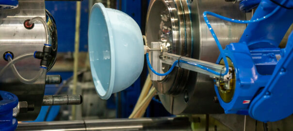
Injection molding is a manufacturing process where molten plastic is injected into a mold cavity. Once the plastic cools and solidifies, the mold opens, and the part is ejected. This process is highly versatile and can produce parts with complex geometries, tight tolerances, and high volumes.


  • Key Components of Injection Molding
  1. Plastic Material: The raw material used, typically thermoplastic or thermosetting polymers.
  2. Mold: A metal cavity that shapes the molten plastic into the desired form.
  3. Injection Unit: Responsible for melting the plastic and injecting it into the mold.
  4. Ejection System: Mechanism that removes the part from the mold after cooling.


  • Advantages of Injection Molding

High Volume Production: Suitable for producing large quantities of parts.

Complex Geometries: Capable of creating intricate shapes and features.

Low Labor Costs: Automated process reduces the need for manual intervention.

Material Efficiency: Minimal waste compared to other manufacturing methods.


  • Common Applications

– Consumer goods (e.g., household items, electronics)

– Automotive components

– Medical devices

– Packaging


  • Design Considerations for Injection Molding

Designing parts for injection molding requires careful consideration of several factors to ensure manufacturability, functionality, and cost-effectiveness.


  • Part Geometry

Wall Thickness: In injection molding, wall thickness plays a crucial role in ensuring part quality, strength, and manufacturability. Ideally, walls should be uniform to promote consistent cooling and prevent defects like warping, sink marks, or internal stresses. Recommended thickness varies by material—ABS (1.2–3.5 mm), Polypropylene (0.8–3.0 mm), and Polycarbonate (1.0–4.0 mm). Avoid abrupt changes in thickness; instead, use gradual transitions or tapers to maintain flow consistency. Overly thick sections can lead to long cooling times and defects, while very thin walls may result in incomplete filling. Always balance strength, material flow, and mold ability when deciding wall  thickness for optimal injection-molded part performance.
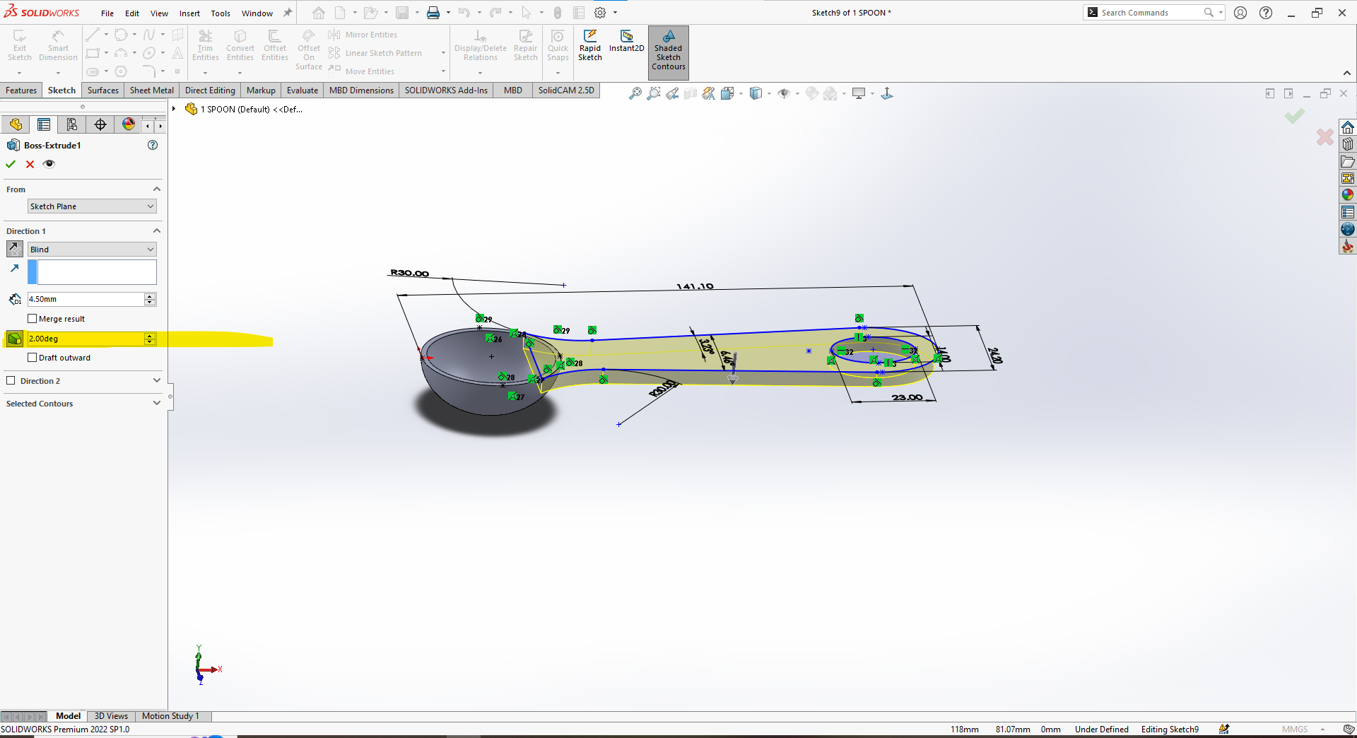
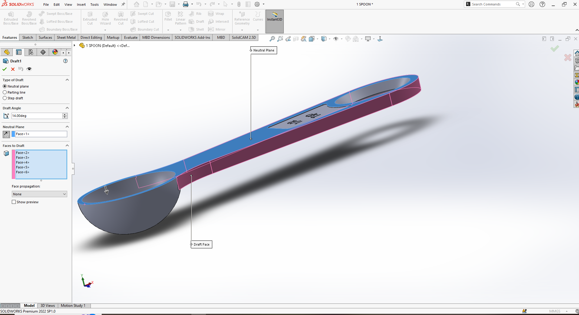
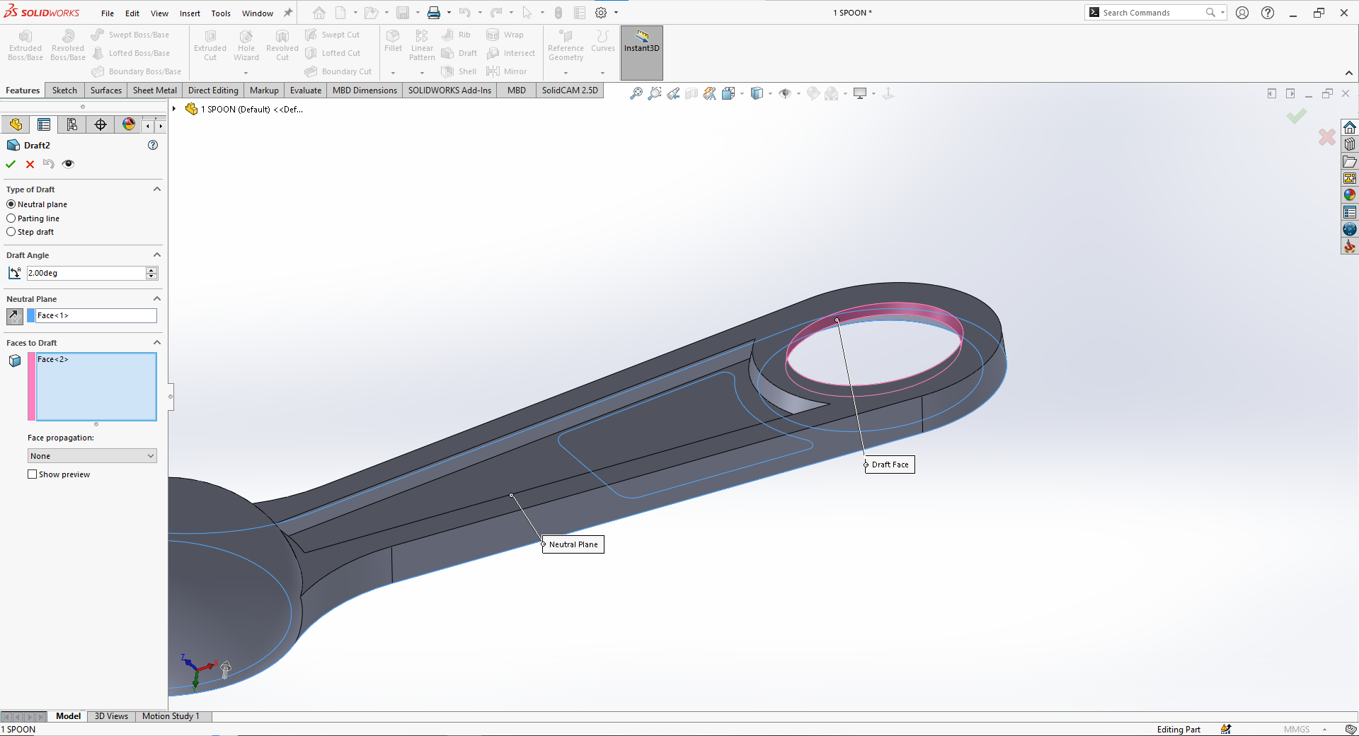
 

Draft Angles: In injection molding, a draft angle is the slight taper applied to vertical surfaces of a part to facilitate easy ejection from the mold. Without adequate draft, parts can stick, causing damage or requiring excessive ejection force. A typical draft angle ranges from 1° to 2° per side, but more may be needed for textured or deep parts. Proper draft improves mold longevity and ensures smooth part release, reducing defects and production delays. All faces perpendicular to the mold opening direction should have draft applied. Designing with draft in mind is essential for moldability, efficiency, and consistent part quality.
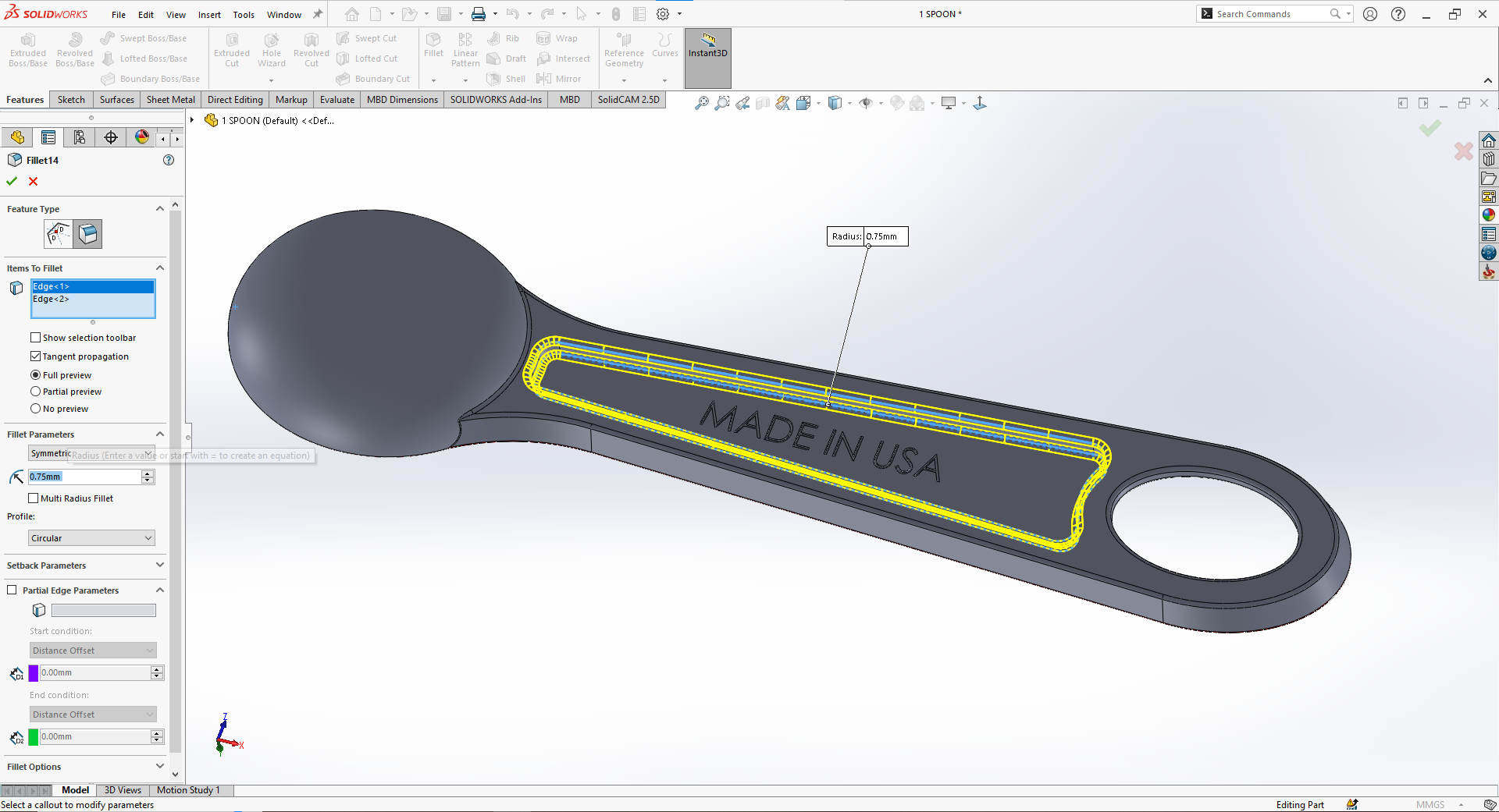
Radius and Fillets: In injection molding, radii and fillets are rounded transitions between surfaces that reduce stress concentrations, improve material flow, and enhance part strength. Sharp corners, especially internal ones, can cause weak points, warping, or incomplete filling. Adding fillets (internal curves) and radii (external curves) helps maintain uniform wall thickness and reduces wear on the mold. A good rule is to use an internal radius of at least 0.5× the wall thickness and match external radii accordingly. These smooth transitions also aid in ejection and overall part aesthetics. Proper use of fillets and radii is essential for durable, high-quality molded parts.

  1. Material Selection

Thermoplastics: Commonly used due to their re-meltable nature (e.g., PP, ABS, PC).

Thermosets: Used for high-temperature applications but are not reusable once set.

Additives: Include fillers, colorants, or reinforcements based on the desired properties.


  1. Tolerances

Dimensional Tolerance: Typically ±0.1mm to ±0.5mm, depending on the material and part size.

Surface Finish: Specify surface roughness (e.g., Ra 1.6 to Ra 12.5) based on the application.


  1. Ejection and Mold Release

Ejector Pins: Ejector pins are critical components in injection molding that push the finished part out of the mold once it has cooled and solidified. Located on the mold’s core side, they apply a controlled force to release the part without causing damage or deformation. Ejector pins are typically round and leave small, often visible marks on non-cosmetic surfaces. Proper pin placement is crucial to avoid warping or sticking, especially on large or thin-walled parts. Designers should provide flat, reinforced areas—called ejector pads—for pin contact. Effective ejection ensures consistent cycle times, part quality, and mold longevity in high-volume manufacturing.

Mold Release: Design features to minimize the need for mold release agents, such as textured surfaces or draft angles.

  1. Ribs and Bosses

Ribs: Ribs in injection molding are thin, protruding features used to reinforce plastic parts without adding excessive material or increasing wall thickness. They enhance structural rigidity, prevent bending, and support other features like bosses or mounting points. To avoid sink marks and warping, ribs should be designed with proper proportions: typically 50–70% of the adjacent wall thickness and no taller than three times that thickness. Draft angles of 0.5–1° and rounded bases help ensure smooth ejection and reduce stress concentrations. Well-designed ribs improve mechanical performance while maintaining moldability, ensuring strong, lightweight, and visually acceptable injection-molded components.

Bosses: Bosses in injection molding are raised cylindrical features typically used for assembly purposes, such as accommodating screws, inserts, or aligning parts. They should be designed with wall thickness no more than 60% of the adjoining wall to avoid sink marks and warping. Adding fillets at the base and reinforcing them with ribs or gussets enhances strength. Proper draft angles (typically 0.5–1°) help with ejection. Well-designed bosses improve part functionality, structural support, and manufacturability.

  1. Holes and Threads

Hole Diameter: In injection molding, hole diameter must be carefully designed to ensure moldability and part strength. Small holes can be difficult to mold accurately, while large holes may weaken the structure. A minimum diameter of 1 mm is recommended, depending on material and wall thickness. Holes should be placed with enough spacing from edges and other features to prevent stress concentration. For deep holes, core pins are used, and slight draft may be added to aid ejection and reduce wear.

Threads: In injection molding, thread diameter must be designed to ensure accurate molding and part strength. External threads are easier to mold than internal ones and should include a draft angle of 1–2° for smooth ejection. For internal threads, collapsible cores or unscrewing mechanisms may be required, increasing mold complexity. Threads should be coarse rather than fine to ensure proper filling and durability. The minimum recommended thread diameter is typically 5 mm, with sufficient clearance to avoid weak walls or distortion.


  1. Snap Fits and Assembly Features

Snap Fits: Design cantilever beams with adequate deflection (0.5mm to 2mm) and return angle (30° to 45°).

Assembly Features: Incorporate alignment features (e.g., guide pins, keyways) for ease of assembly.

  1. Mold Flow and Fill Analysis
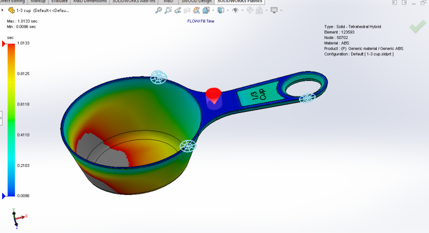
Flow Length-to-Thinness Ratio: Optimize the flow path to ensure even filling and minimize material pressure.

Weld Lines: Avoid placing critical features where weld lines may form, as they can weaken the part.

  1. Cooling and Shrinkage

Cooling Time: Ensure sufficient cooling time to prevent warping and dimensional inaccuracies.

Shrinkage: Account for material shrinkage (typically 0.1% to 2%) in your design.

  1. Aesthetics and Branding
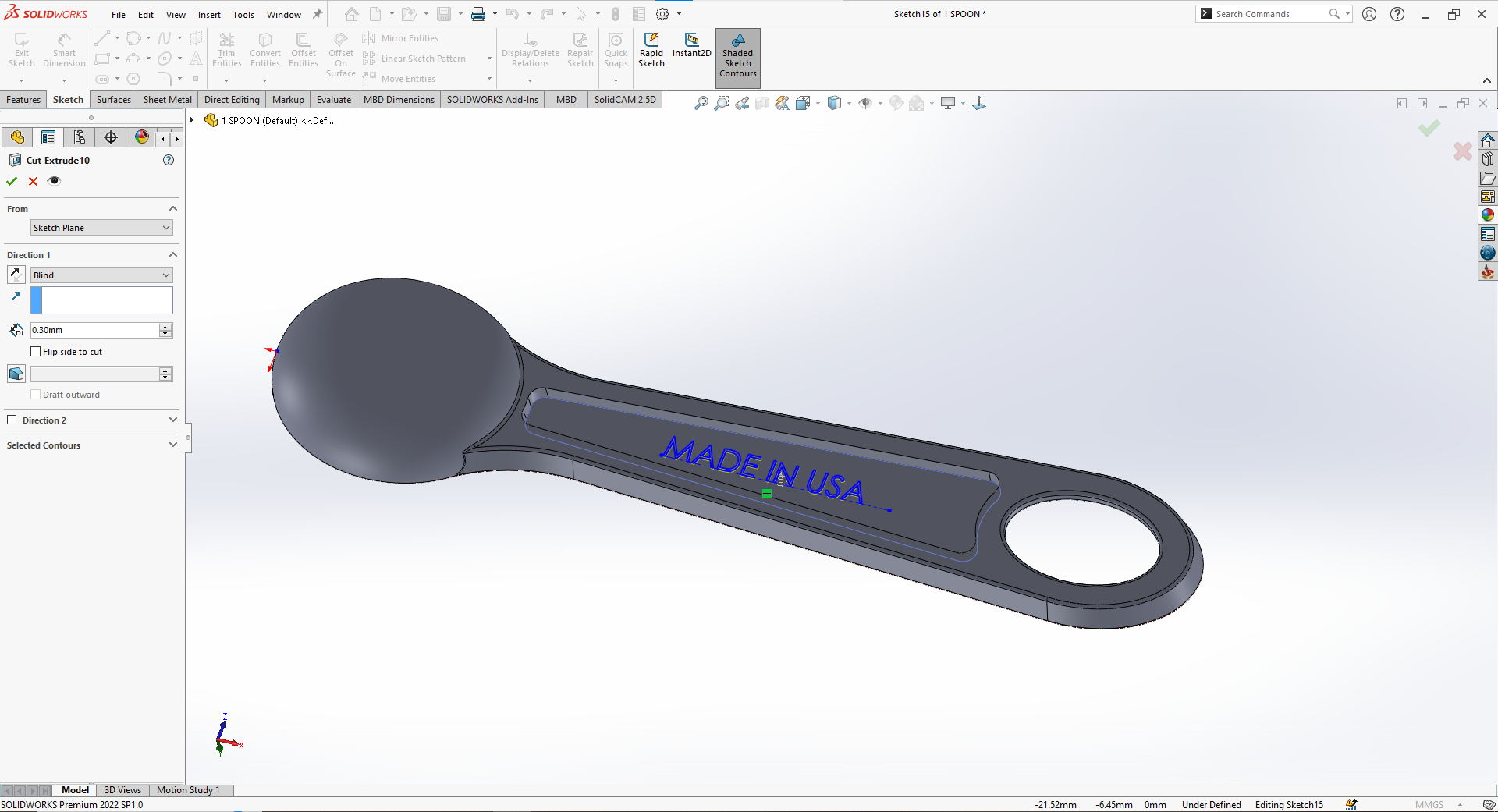
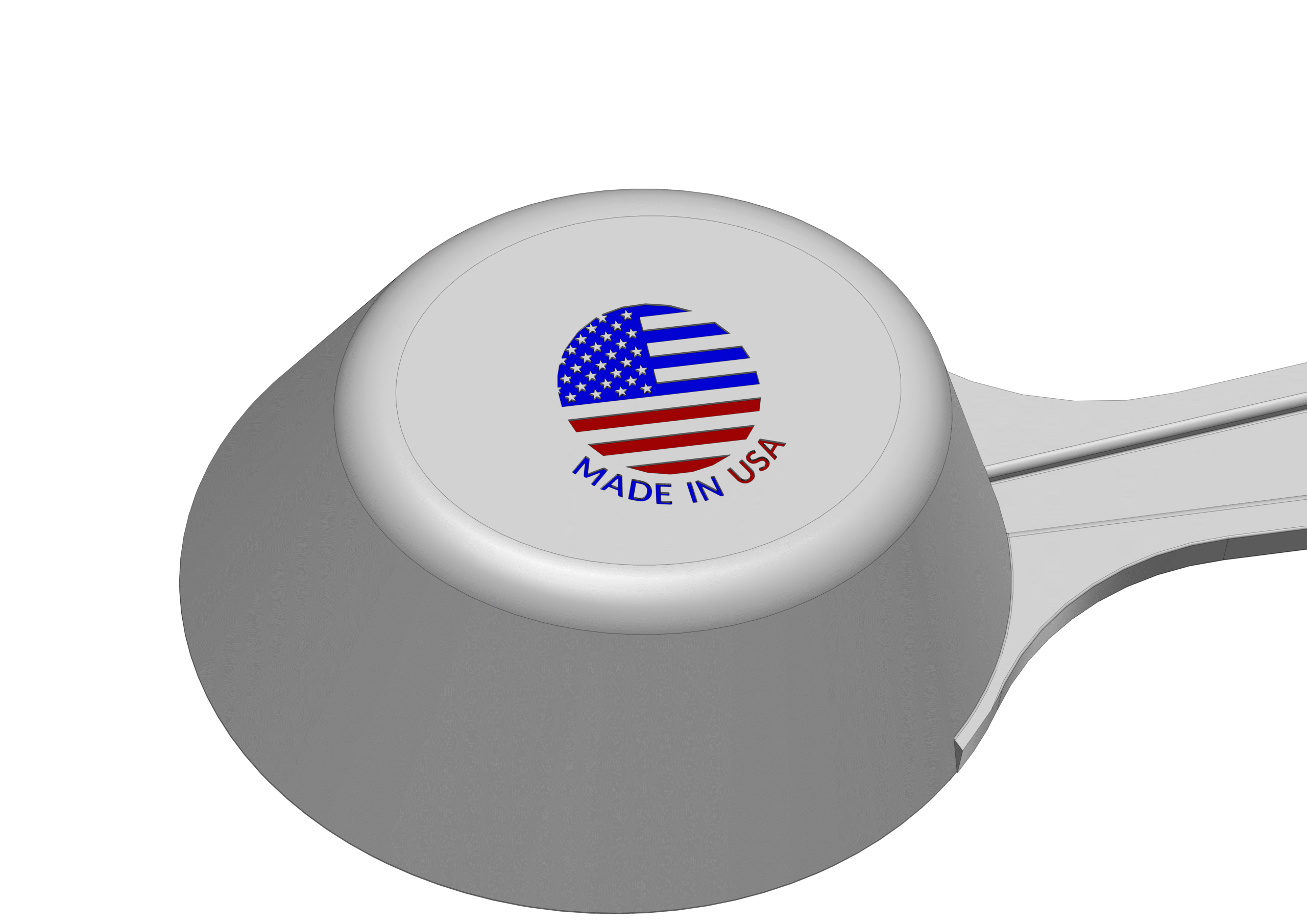
 

Logos and Markings: In injection molding, logo engraving should be designed with clear, moldable dimensions to ensure readability and ease of manufacturing. The minimum line width (diameter) for engraved features is typically 0.25 mm, depending on the material and mold precision. Engravings should not be too deep—usually 0.1 to 0.3 mm—to avoid sink marks and ensure smooth ejection. Placement on flat, non-critical surfaces is ideal. Adequate draft angles (at least 1°) help prevent damage during demolding and improve logo clarity.

  • Material Selection for Injection Molding

The choice of material is critical for the performance, cost, and manufacturability of your part.

  • Common Materials
  1. Polypropylene (PP): Lightweight, flexible, and chemical-resistant.
  2. Acrylonitrile Butadiene Styrene (ABS): Impact-resistant and suitable for high-temperature applications.
  3. Polycarbonate (PC): Transparent, impact-resistant, and suitable for optical applications.
  4. Polyethylene (PE): Low-cost, flexible, and chemical-resistant.
  5. Polyester (PET): High-strength, rigid, and suitable for packaging.
  • Material Properties to Consider

Mechanical Properties: Tensile strength, impact resistance, and flexural modulus.

Thermal Properties: Heat deflection temperature (HDT) and thermal conductivity.

Chemical Resistance: Compatibility with chemicals and cleaning agents.

Optical Properties: Transparency, gloss, and UV resistance.

  • Additives and Fillers

Reinforcements: Glass fibers for increased strength and stiffness.

Fillers: Minerals like calcium carbonate to reduce material costs.

Colorants: Pigments or masterbatches for custom colors.

UV Stabilizers: To prevent degradation from UV exposure.

  • Sustainability Considerations

Recyclability: Choose materials that are recyclable or biodegradable.

Bioplastics: Consider PLA (Polylactic Acid) or PHA (Polyhydroxyalkanoates) for eco-friendly applications.

Material Efficiency: Optimize part weight and thickness to minimize material usage.

  • Design for Manufacturability (DFM)

Design for Manufacturability (DFM) is a critical aspect of injection molding that ensures your part can be produced efficiently and cost-effectively.

  • Key DFM Principles
  1. Simplify the Design: Avoid unnecessary complexity that could increase tooling costs or lead to manufacturing defects.
  2. Minimize Undercuts: Undercuts require side actions in the mold, which increase tooling complexity and cost.
  3. Avoid Thin Walls: Ensure wall thickness is consistent and within recommended limits to prevent warping and sink marks.
  4. Use Standard Features: Standardize features like bosses, ribs, and snaps to reduce design variability.
  • Moldability Analysis

Flow Analysis: Use simulation tools to analyze how molten plastic flows into the mold cavity.

Pressure Drop: Ensure that the pressure drop is within acceptable limits to avoid material degradation.

Cooling Analysis: Optimize cooling channels to ensure uniform cooling and minimize warping.

  • Design for Assembly (DFA)

Snap Fits: Use snap fits to eliminate the need for fasteners.

Alignment Features: Incorporate guide pins, keyways, or chamfers to facilitate easy assembly.

Modular Design: Design parts that can be easily assembled into a complete product.

  • Cost Reduction Strategies

Reduce Material Usage: Optimize part weight and thickness to minimize material costs.

Simplify Tooling: Avoid complex mold features that increase tooling costs.

Increase Production Volume: Take advantage of economies of scale by producing larger batches.

  • Tooling and Mold Design

The mold is a critical component of the injection molding process, and its design directly impacts the quality, cost, and lead time of your part.

  • Key Components of a Mold
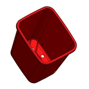
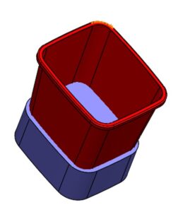
  1. Cavity: The part of the mold that shapes the plastic into the desired form.
  2. Core: The part of the mold that creates holes or recesses in the part.
  3. Runner System: Channels that direct molten plastic from the injection unit to the mold cavity.
  4. Gates: Points where molten plastic enters the mold cavity.
  5. Ejector Pins: Mechanisms that push the part out of the mold after cooling.


  • Mold Types
  1. Single-Cavity Mold: Produces one part per cycle. Ideal for low-volume production.
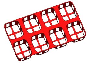
  2. Multi-Cavity Mold: Produces multiple parts per cycle. Ideal for high-volume production.
  3. Family Mold: Produces multiple parts of similar size or shape. Reduces tooling costs.
  4. Hot Runner Mold: Uses insulated runners to keep the plastic molten between shots. Reduces material waste.


  • Mold Materials
  1. Steel: Most common mold material due to its durability and cost-effectiveness.
  2. Aluminum: Used for prototype molds or low-volume production due to its faster machining time.
  3. Beryllium Copper: Used for high-wear areas due to its high thermal conductivity.


  • Mold Surface Finish

Polishing: Improves part quality and reduces mold wear.

Texturing: Creates surface textures for aesthetic or functional purposes.

Coating: Applies wear-resistant or corrosion-resistant coatings to critical areas.


  • Mold Maintenance

Cleaning: Regularly clean the mold to prevent contamination and material buildup.

Lubrication: Lubricate moving parts to reduce wear and tear.

Inspection: Inspect the mold for damage or wear and perform repairs as needed.


  • Surface Finishing and Textures

Surface finishing and textures play a crucial role in the aesthetics and functionality of injection-molded parts.


  • Common Surface Finishes
  1. Polished Finish: Achieved by polishing the mold cavity to a high gloss. Ideal for optical applications.
  2. Textured Finish: Creates a specific surface texture for grip, aesthetics, or functionality.
  3. Matte Finish: Provides a dull, non-reflective surface. Ideal for hiding mold marks or imperfections.
  4. Etched Finish: Creates a fine, detailed texture using chemical etching.


  • Texture Patterns
  1. Fine Texture: Provides a smooth, low-gloss surface.
  2. Medium Texture: Offers a balanced combination of aesthetics and functionality.
  3. Coarse Texture: Ideal for applications requiring high grip or durability.


  • Functional Textures

Grip Textures: Used on handles, grips, and other areas requiring traction.

Ventilation Textures: Create airflow or drainage in applications like filters or vents.

Aesthetic Textures: Enhance the visual appeal of the part.


  • Application Methods
  1. Mold Texturing: Textures are incorporated directly into the mold cavity.
  2. Post-Molding Texturing: Textures are applied after molding using processes like laser etching or pad printing.
  3. Insert Molding: Textures are molded into inserts that are then assembled into the final part.


  • Assembly and Post-Molding Operations

Many injection-molded parts require additional assembly or post-molding operations to meet their functional requirements.


  • Assembly Methods
  1. Snap Fits: Use cantilever beams or other snap-fit features to eliminate the need for fasteners.
  2. Ultrasonic Welding: Join parts using high-frequency vibrations to create a strong bond.
  3. Adhesive Bonding: Use adhesives to join parts, especially when different materials are involved.
  4. Screw or Rivet Assembly: Use mechanical fasteners for applications requiring high strength or adjustability.


  • Post-Molding Operations
  1. Printing: Apply labels, logos, or other graphics using screen printing, pad printing, or laser marking.
  2. Painting: Apply paint for aesthetic or functional purposes, such as color matching or UV resistance.
  3. Plating: Apply metal coatings for conductivity, corrosion resistance, or aesthetics.
  4. Machining: Perform secondary machining operations like drilling, tapping, or grinding for precision features.


  • Automation in Assembly

Robotic Assembly: Use robots to automate repetitive tasks like screw driving or welding.

Vision Systems: Use vision systems to inspect and guide assembly operations.

Conveyor Systems: Use conveyor systems to move parts through the assembly line efficiently.


  • Design for Assembly (DFA)

Simplify the Design: Minimize the number of parts and fasteners to reduce assembly time and cost.

Modular Design: Design parts that can be easily assembled into a complete product.

Alignment Features: Incorporate guide pins, keyways, or chamfers to facilitate easy alignment during assembly.


  • Testing and Validation

Before moving to mass production, it’s essential to test and validate your design to ensure it meets the required performance, safety, and quality standards.


  • Types of Testing
  1. Mechanical Testing: Evaluate the part’s strength, stiffness, and impact resistance.
  2. Thermal Testing: Test the part’s performance under extreme temperatures.
  3. Chemical Resistance Testing: Assess the part’s resistance to chemicals and cleaning agents.
  4. Optical Testing: Evaluate the part’s clarity, gloss, and UV resistance.
  5. Functional Testing: Test the part’s functionality in its intended application.


Rapid Prototyping: Use 3D printing or CNC machining to create prototypes for testing.

Design Iteratio: Refine the design based on test results and feedback.

Design Freeze: Finalize the design once all issues have been resolved.


  • Quality Control

Inspection: Regularly inspect parts for defects or variations.

Dimensional Measurement: Measure critical dimensions to ensure compliance with specifications.

Statistical Process Control (SPC): Monitor the production process to maintain consistent quality.


As environmental concerns grow, designing sustainable injection-molded parts is becoming increasingly important.


  • Key Sustainability Considerations
  1. Material Selection: Choose materials that are recyclable, biodegradable, or made from renewable resources.
  2. Material Efficiency: Optimize part weight and thickness to minimize material usage.
  3. Energy Efficiency: Design parts that can be produced using less energy and water.
  4. End-of-Life Design: Design parts for disassembly, recycling, or biodegradation.


  • Bioplastics

PLA (Polylactic Acid): A biodegradable thermoplastic made from renewable resources like corn starch or sugarcane.

PHA (Polyhydroxyalkanoates): A biodegradable thermoplastic produced from bacterial fermentation.

PBAT (Polybutylene Adipate-co-Butylene Terephthalate): A biodegradable thermoplastic used for flexible applications.


  • Recyclable Materials

Recycled Plastics: Use post-consumer recycled (PCR) or post-industrial recycled (PIR) materials.

Material Identification: Use material identification codes to facilitate sorting and recycling.


  • Design for Recyclability

Simplify the Design: Avoid complex geometries or multiple materials that complicate recycling.

Material Separation: Design parts that can be easily disassembled and separated into different materials.

Avoid Contaminants: Minimize the use of additives, coatings, or adhesives that can contaminate recycled materials.


  • Cost Considerations and Optimization

Understanding the cost drivers in injection molding is essential for optimizing your design and reducing production expenses.


  • Key Cost Drivers
  1. Tooling Costs: The cost of designing and building the mold is a significant upfront expense.
  2. Material Costs: The cost of the plastic material used to produce the part.
  3. Production Volume: Higher production volumes reduce the per-unit cost due to economies of scale.
  4. Complexity: Complex geometries, undercuts, and multiple cavities increase tooling and production costs.


  • Cost Reduction Strategies
  1. Simplify the Design: Avoid unnecessary complexity that increases tooling and production costs.
  2. Use Standard Features: Standardize features like bosses, ribs, and snaps to reduce design variability.
  3. Optimize Material Usage: Minimize material waste by optimizing part weight and thickness.
  4. Use Recycled Materials: Incorporate recycled plastics to reduce material costs.
  5. Increase Production Volume: Take advantage of economies of scale by producing larger batches.


  • Total Cost of Ownership (TCO)

Material Costs: The cost of the plastic material over the product’s lifecycle.

Tooling Costs: The upfront cost of designing and building the mold.

Production Costs: The cost of producing the part, including labor, energy, and overhead.

Post-Molding Costs: The cost of additional operations like assembly, painting, or packaging.

Warranty and Repair Costs: The cost of repairing or replacing defective parts.


  • Case Studies and Examples

Real-world examples provide valuable insights into the challenges and opportunities of designing parts for injection molding.


  • Case Study 1: Consumer Electronics Housing

Challenge: Design a lightweight, impact-resistant housing for a portable electronic device.

Solution: Use ABS for its high impact resistance and process ability. Incorporate ribs and gussets for added stiffness without increasing material usage.

Outcome: A durable, cost-effective housing that meets the required performance and aesthetic standards.


  • Case Study 2: Medical Device Component

Challenge: Design a clear, autoclavable component for a medical device.

Solution: Use PC for its transparency and high heat resistance. Incorporate textured surfaces for grip and alignment features for easy assembly.

Outcome: A component that meets strict medical standards for clarity, sterility, and functionality.


  • Case Study 3: Automotive Part

Challenge: Design a lightweight, heat-resistant part for an automotive application.

Solution: Use a glass-filled PA6 for its high strength, stiffness, and heat resistance. Optimize the design for minimal material usage and easy assembly.

Outcome: A cost-effective, high-performance part that meets the demanding requirements of the automotive industry.


  • Best Practices and Future Trends

Adhering to best practices and staying informed about future trends ensures that your designs remain competitive and innovative.


  • Best Practices
  1. Collaborate with Mold Makers: Work closely with mold makers to ensure your design is manufacturable.
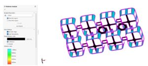
  2. Use Simulation Tools: Utilize mold flow and structural analysis tools to optimize your design.
  3. Consider Sustainability: Design parts with sustainability in mind, using recyclable or biodegradable materials.
  4. Iterate and Refine: Continuously refine your design based on testing and feedback.


  • Future Trends
  1. Advanced Materials: Development of new materials with enhanced properties, such as self-healing plastics.
  2. Digital Manufacturing: Increased use of digital tools for design, simulation, and production.
  3. Circular Economy: Focus on designing parts for recyclability, reusability, and biodegradability.
  4. Additive Manufacturing: Integration of additive manufacturing techniques with injection molding for hybrid production methods.

By following the insights and guidelines outlined in this guide, you can design injection-molded parts that are functional, cost-effective, and sustainable. Whether you’re a seasoned designer or just starting out, understanding the principles of injection molding will empower you to create innovative solutions that meet the demands of modern manufacturing.

From Idea to Mold: Expert Guide to Injection Molded Part Design

Injection molding is one of the most widely used manufacturing processes for producing plastic parts. Known for its precision, scalability, and cost-effectiveness, it’s the backbone of countless industries, from consumer goods to automotive. However, getting a perfect part off the press isn’t just about injecting molten plastic into a mold—it starts much earlier, at the design stage.

In this article, we’ll walk through key considerations in designing parts for injection molding, covering everything from basic principles to material selection, mold design, and emerging trends. Whether you’re an engineer, product developer, or just curious about how plastic products are made, this guide will equip you with essential insights.

Understanding the Injection Molding Process

Before diving into design specifics, it’s important to understand how injection molding works. In simple terms, the process involves melting plastic pellets, injecting them under high pressure into a mold cavity, cooling the plastic until it solidifies, and then ejecting the finished part.

Here’s a quick step-by-step outline:


  1. Clamping: The two halves of the mold are closed tightly.

  2. Injection: Molten plastic is injected into the mold cavity.

  3. Cooling: The plastic cools and solidifies into the shape of the cavity.

  4. Ejection: The mold opens and ejector pins push the part out.

  5. Repeat: The cycle starts again, making injection molding highly efficient for mass production.

Key Design Considerations for Injection Molded Parts

Part Geometry & Wall Thickness

One of the most critical factors in part design is maintaining uniform wall thickness. Thick sections can lead to sink marks or warping, while overly thin walls may compromise strength or lead to incomplete fills. A balanced design ensures even cooling and minimizes internal stresses.

Draft Angles

Draft angles—slight tapers added to the vertical walls of your part—are essential for smooth ejection. Without them, parts can stick to the mold, causing damage or requiring excessive force to remove.

Tolerances & Shrinkage

Injection molding offers tight tolerances, but designers must account for material shrinkage, which occurs as the plastic cools. Different materials have different shrink rates, so collaborating with molders early helps establish realistic tolerances.

Design for Manufacturability (DFM)

Designing for manufacturability is about making your part as straightforward to produce as possible. This often means:

  • Minimizing undercuts or complex features that require special tooling.

  • Adding ribs or gussets to reinforce parts without adding unnecessary mass.

  • Designing features like snap-fits or living hinges carefully to maintain durability.

Proper DFM reduces mold complexity, lowers costs, and speeds up production.

Smart Material Selection

Not all plastics are created equal. Some are flexible, others rigid; some withstand high temperatures, while others offer superior chemical resistance. Your choice affects:

  • Shrinkage and thermal expansion

  • Impact strength and flexibility

  • Appearance and texture

For example, choosing a glass-filled nylon might provide extra stiffness but require adjustments for higher shrink rates.

Tooling & Mold Design Essentials

Good part design pairs with thoughtful mold design. This includes:

  • Runner systems & gates: Direct how plastic flows into the cavity.

  • Ejector pins: Help remove parts cleanly without deforming them.

  • Cooling channels: Maintain consistent temperatures for uniform part quality.

You’ll also need to decide between single-cavity molds (making one part per cycle) or multi-cavity molds (producing multiple identical parts simultaneously). While multi-cavity molds increase output, they require more precise balance and often higher upfront costs.

Planning for Assembly & Post-Processing

If your part will be assembled with others, consider adding features like:

  • Snap fits

  • Bosses for screws

  • Alignment features

Also plan for post-molding operations such as painting, pad printing, or ultrasonic welding. Designing with these in mind ensures your parts integrate smoothly downstream.

Testing, Validation & Prototyping

Before committing to expensive steel tooling, many teams prototype designs using 3D printing or CNC-machined soft tools. This helps identify design flaws early. Later, mechanical and thermal testing verify that parts meet performance standards.

Balancing Performance & Cost

It’s no secret that design choices impact production costs. Complex geometries might look impressive but often lead to expensive molds. Simplifying designs where possible or reducing unnecessary features can keep projects on budget without compromising functionality.

Conclusion: Designing for Success

From idea to mold, thoughtful design is what turns a concept into a reliable, cost-effective, and beautiful plastic part. By understanding the fundamentals of injection molding, prioritizing manufacturability, selecting the right materials, and planning for the entire lifecycle of the product, you set your project up for success.

Whether you’re launching a new consumer product or refining a critical automotive component, designing with these principles in mind ensures your parts perform well—both on the shop floor and in the hands of your customers.

Comparative Analysis of Resin Transfer Molding vs. Other Composite Manufacturing Techniques for Off-Highway Applications

Composite materials have become essential in the off-highway sector, offering significant benefits such as reduced weight, increased strength, and improved durability. Resin Transfer Molding (RTM) is one of the leading methods for injection molding manufacturing composite components, but it is not the only option. This article provides a comparative analysis of RTM against other composite manufacturing techniques, such as vacuum infusion, hand lay-up, and autoclave molding, focusing on their respective advantages, challenges, and suitability for off-highway applications.

Resin Transfer Molding (RTM): Overview and Advantages

Resin Transfer Molding (RTM) is a closed-mold process that involves injecting molding resin into a mold containing a pre-formed fiber reinforcement. The process is well-known for producing high-quality, complex parts with excellent surface finishes. RTM offers several key advantages, particularly for off-highway applications:

  • Precision and Repeatability: RTM allows for precise control over resin flow and fiber placement, resulting in highly consistent and repeatable parts. This precision is crucial for off-highway components that must meet stringent performance standards.

  • Complex Geometry: RTM can produce parts with complex shapes and integrated features, making it ideal for manufacturing intricate components such as vehicle body panels, structural parts, and enclosures.

  • Surface Finish: The closed-mold nature of RTM results in a smooth surface finish on both sides of the part, reducing the need for post-processing and enhancing the aesthetic appeal of visible components.

However, RTM also presents some challenges, including the need for precise mold design and the potential for high tooling costs, especially for low-volume production runs.

Vacuum Infusion: A Flexible Alternative

Vacuum infusion is another closed-mold process, similar to RTM, but with some distinct differences. In vacuum infusion, the resin is drawn into the mold using vacuum pressure, rather than being injected under pressure as in RTM.

  • Lower Tooling Costs: Vacuum infusion typically requires less expensive tooling compared to RTM, making it a more cost-effective option for lower-volume production runs or large parts.

  • Material Flexibility: The vacuum infusion process can accommodate a wide range of fiber types and resin systems, offering flexibility in material selection based on the specific needs of the application.

  • Improved Fiber Wet-Out: The vacuum pressure helps to ensure complete fiber wet-out, which can enhance the mechanical properties of the final part.

However, vacuum infusion may not be as precise as RTM, particularly for parts with very complex geometries. The surface finish is also typically not as smooth as what can be achieved with RTM, which may require additional finishing processes.

Hand Lay-Up: Traditional and Cost-Effective

Hand lay-up is one of the oldest and simplest composite manufacturing techniques. It involves manually placing layers of fiber reinforcement in an open mold and applying resin by hand.

  • Low Capital Investment: Hand lay-up requires minimal equipment and tooling, making it the most cost-effective option for small-scale production and prototyping.

  • Flexibility in Design: The process is highly adaptable, allowing for on-the-fly adjustments to fiber orientation and resin application, which can be beneficial for custom or one-off parts.

However, hand lay-up is labor-intensive and less consistent than automated processes like RTM. The quality of the final part is highly dependent on the skill of the operator, and the process is generally unsuitable for high-volume production due to its slow cycle times.

Autoclave Molding: High-Performance Composites

Autoclave molding is a process used to produce high-performance composite parts, particularly in aerospace and defense applications. The process involves placing a resin-impregnated fiber preform into a mold, which is then cured under heat and pressure in an autoclave.

  • Superior Mechanical Properties: The combination of high pressure and temperature during the autoclave process results in parts with exceptional mechanical properties, including high strength and stiffness.

  • High-Quality Surface Finish: Like RTM, autoclave molding can produce parts with excellent surface finishes, reducing the need for post-processing.

However, autoclave molding is expensive and time-consuming, with high tooling and operational costs. It is typically reserved for applications where performance is the primary concern, and cost is less of an issue.

Suitability for Off-Highway Applications

When selecting a composite injection molding manufacturing process for off-highway applications, several factors must be considered, including cost, production volume, part complexity, and performance requirements.

  • RTM is well-suited for producing high-performance, complex parts in medium to high volumes. Its precision and ability to produce high-quality finishes make it ideal for structural components, body panels, and enclosures in off-highway vehicles.

  • Vacuum Infusion offers a balance between cost and performance, making it a good choice injection molding for larger parts or lower-volume production runs where material flexibility is important.

  • Hand Lay-Up is best suited for prototyping, custom parts, or small-scale production, where cost is a major concern, and performance requirements are less stringent.

  • Autoclave Molding is the go-to process for high-performance parts that must meet the most demanding mechanical and environmental conditions, though it is generally not cost-effective for high-volume production in the off-highway sector.

Conclusion

Choosing the right composite manufacturing process is crucial for optimizing the performance, cost, and production efficiency of off-highway vehicle components. While RTM offers several advantages, particularly for complex and high-performance parts, other methods like vacuum infusion, hand lay-up, and autoclave injection molding each have their own strengths and are better suited to specific applications. By understanding the benefits and limitations of each technique, plastic manufacturers can make informed decisions that align with their production goals and the specific needs of the off-highway injection molding industry.

Top 6 Supplier Databases to Find Qualified Injection Molding, Thermoforming, and Fiberglass Suppliers

  1. ThomasNet

    • Website: thomasnet.com

    • Features:

      • Comprehensive database with over 500,000 suppliers.

      • Advanced filtering by location, certification, and services.

      • Access to product catalogs, reviews, and direct contact information.

  2. MFG.com

    • Website: mfg.com

    • Features:

      • Global manufacturing marketplace.

      • Post RFQs and receive competitive bids.

      • Supplier ratings and feedback to help in decision-making.

  3. GlobalSpec

    • Website: globalspec.com

    • Features:

      • Engineering-focused supplier database.

      • Advanced search capabilities by certifications, location, and capabilities.

      • Detailed supplier information for plastics and composites industries.

  4. Maker’s Row

    • Website: makersrow.com

    • Features:

      • Focus on U.S.-based manufacturers.

      • Ideal for small to mid-sized businesses.

      • Transparent supplier profiles, project portfolios, and customer reviews.

  5. Kompass

    • Website: us.kompass.com

    • Features:

      • Global B2B directory.

      • Advanced search filters by product type, industry, and location.

      • Extensive supplier information across various industries, including plastics and composites.

  6. IQS Directory

    • Website: iqsdirectory.com

    • Features:

      • Focus on North American manufacturers.

      • Detailed company profiles and direct contact details.

      • Search by industry, material, or manufacturing process.

Conclusion

Utilizing these top 6 supplier databases can help you efficiently connect with qualified suppliers for injection molding, thermoforming, and fiberglass services. Whether you need cost-effective solutions, U.S.-based manufacturing, or specialized capabilities, these databases provide the resources to find reliable and experienced partners for your projects.

Plastic Injection Molding: Your Gateway to Successful Product Manufacturing

As an entrepreneur or business owner looking to launch a new product, you’re likely exploring various manufacturing options. One process you absolutely must consider is plastic injection molding. This versatile manufacturing method can be the key to bringing your product ideas to life, regardless of your industry or scale of production.

Why Plastic Injection Molding is Perfect for Entrepreneurs

  1. Scalability: Start small with prototype runs and scale up to full production as demand grows.

  2. Versatility: Suitable for a vast range of products across numerous industries.

  3. Cost-effectiveness: High initial tooling costs are offset by low per-unit costs in larger production runs.

  4. Quality and Consistency: Produce high-quality, identical parts with tight tolerances.

  5. Design Flexibility: Create complex shapes and integrate multiple features into a single part.

The Ubiquity of Injection Molded Products

Look around you. Chances are, most of the plastic objects you see were manufactured using injection molding. From the pen in your hand to the keyboard you’re typing on, from the chair you’re sitting in to the car you drive – injection molded parts are everywhere. As an entrepreneur, this ubiquity should excite you. It means that whatever your product idea, can likely make it a reality.

Industry-Specific Examples and Applications

Let’s explore how various industries leverage molding, providing you with ideas and inspiration for your own product:

1. Consumer Electronics

  • Example: Smartphone cases

  • Details: Injection molding allows for precise cutouts for buttons and ports, integration of multiple materials for shock absorption, and the ability to produce millions of identical units quickly.

  • Entrepreneurial Opportunity: Consider designing unique, feature-rich phone accessories or cases for niche markets.

2. Automotive

  • Example: Dashboard components

  • Details: Injection molding produces durable, heat-resistant parts with integrated clips and fasteners, reducing assembly time and costs.

  • Entrepreneurial Opportunity: Develop aftermarket parts or innovative automotive accessories.

3. Medical Devices

  • Example: Disposable syringes

  • Details: Injection molding ensures sterility, precise measurements, and the ability to produce millions of units cost-effectively.

  • Entrepreneurial Opportunity: Create innovative medical tools or home health devices.

4. Toys and Games

  • Example: Building blocks (like LEGO)

  • Details: Injection molding provides the precision necessary for interlocking parts, vibrant colors, and the durability to withstand rough play.

  • Entrepreneurial Opportunity: Design educational toys or game pieces with unique features.

5. Home Goods

  • Example: Reusable food storage containers

  • Details: Injection molding allows for airtight seals, microwaveable and dishwasher-safe materials, and stackable designs.

  • Entrepreneurial Opportunity: Develop innovative kitchen gadgets or organization solutions.

Recent Technological Advancements and Trends

As an entrepreneur, staying ahead of the curve is crucial. Here are some recent advancements in that could give your product an edge:

  1. 3D-Printed Molds: Rapid prototyping and small production runs are now more accessible than ever.

  2. Smart Connected Molding Machines: IoT-enabled machines provide real-time monitoring and adjustments, ensuring consistent quality.

  3. Sustainable Materials: Bio-based plastics and recycled materials are becoming increasingly popular, appealing to eco-conscious consumers.

  4. Micromolding: Producing incredibly small parts for industries like medical devices and electronics.

  5. Gas-Assisted Injection Molding: Creating hollow parts to reduce weight and material usage.

From Concept to Production: Your Journey with Injection Molding

  1. Idea Generation: Sketch your product idea. Consider how injection molding can help realize complex shapes or integrate multiple features.

  2. Design for Manufacturing: Work with a design engineer to optimize your product. This may include adding draft angles, ribs for strength, or snap-fit assembly features.

  3. Material Selection: Choose from a wide range of thermoplastics, each with unique properties. An experienced molder can help you select the best material for your application.

  4. Prototyping: Start with 3D-printed prototypes or low-volume injection molded parts to test your design.

  5. Tooling: Invest in a production mold. While costly upfront, a well-made mold can produce millions of parts.

  6. Initial Production Run: Start with a small production run to test the market and refine your product if necessary.

  7. Scaling Up: As demand grows, increase your production volume. Injection molding excels at high-volume production, with costs per unit decreasing as volume increases.

Why You Should Definitely Consider Injection Molding

  1. Proven Technology: Injection molding has been refined over decades, resulting in a reliable, well-understood process.

  2. Wide Network of Suppliers: There’s a vast network of injection molders, ensuring competitive pricing and specialized expertise.

  3. Customization Options: From colors to textures to multi-material parts, injection molding offers numerous ways to make your product unique.

  4. Quality Control: The repeatability of injection molding ensures consistent quality across production runs.

  5. Speed to Market: Once your mold is made, you can produce thousands of parts quickly, allowing you to respond rapidly to market demand.

Cost Model for Pricing Plastic Injection Molded Parts

Plastic injection molding is a widely used manufacturing process for producing high-quality, mass-produced plastic parts. Developing an accurate cost model is essential for determining part prices that cover production expenses while remaining competitive. In this article, we’ll walk through the key components of a cost model for plastic injection molded parts, explaining how to calculate cycle time, injection flow rate, ejection time, and other critical factors. We’ll also explore how material costs, machine rates, labor, tooling, and overheads influence the final price.

Key Components of a Plastic Injection Molding Cost Model

A comprehensive cost model involves understanding the full production process, from the initial injection of molten plastic to the ejection of the cooled part. The following sections break down each part of this process, providing formulas and methodologies to estimate costs accurately.


1. Cycle Time Estimation

Cycle time refers to the total time required to produce one part and consists of three main phases:

  • Injection time: The time it takes to inject molten plastic into the mold cavity.

  • Cooling time: The time required for the part to cool enough to be ejected from the mold.

  • Ejection time: The time taken to eject the cooled part from the mold.

This formula captures the core components of the injection molding process and helps you estimate how long each part takes to produce. Let’s explore how to calculate each part of this formula.

Cycle Time formula

a. Injection Time Calculation

The injection time is influenced by the volume of the part, the machine’s injection speed, and the material’s viscosity.

  • Part Volume: The volume of the plastic part being produced, measured in cubic centimeters (cm³).

  • Injection Flow Rate: The speed at which molten plastic is injected into the mold, determined by machine settings and material properties.

Plastic Injection Molding: Injection Time Formula

Factors affecting injection time:

  • Machine capacity: Larger machines can inject more material at once, increasing the flow rate.

  • Material viscosity: High-viscosity materials, like polycarbonate, are more resistant to flow, resulting in longer injection times.

  • Part geometry: Thin-walled or complex geometries slow down the injection process, as they require more precise control to prevent defects.

Injection Time Calculation Formula Example

For example, if the part volume is 50 cm³ and the machine’s injection flow rate is 25 cm³/sec, the injection time is:

b. Cooling Time Calculation

Cooling time is often the longest part of the cycle and is crucial to ensure the part solidifies properly without defects like warping.

Injection Molding Cooling Time Calculation

Where:

  • Wall thickness is the thickness of the part’s walls (in cm).

  • Thermal diffusivity constant (a) is a material property indicating how fast heat spreads.

  • T_mold, T_material melt, and T_ejection are the temperatures of the mold, the material in its melted state, and the material when it is ejected, respectively.

This formula is useful for estimating how long the part needs to stay in the mold before it’s solid enough to eject. The thicker the part, the longer the cooling time.

For a wall thickness of 0.2 cm, assuming the material is ABS (a = 0.00015 cm²/sec), with mold, material melt, and ejection temperatures of 50°C, 230°C, and 90°C, respectively, cooling time might result in approximately 15 seconds.

c. Ejection Time Calculation

Ejection time refers to the time required to remove the cooled part from the mold cavity. This includes the mechanical time taken by the ejector pins or air systems to push the part out of the mold.

  • Ejection Delay Time: Time for the mold to open and prepare for part removal.

  • Mechanical Ejection Time: Time for the ejector pins or other mechanical systems to push the part out.

Ejection time is generally short, usually between 1 and 5 seconds, depending on the complexity of the part and the number of ejector pins used.

Factors affecting ejection time:

  • Part geometry: More complex shapes require more careful ejection to avoid damage.

  • Mold design: The number and placement of ejector pins, as well as the presence of undercuts, influence ejection time.

  • Material shrinkage: Materials with high shrinkage can contract around the mold, making ejection slower and more difficult.

For example, if ejection delay takes 1 second and mechanical ejection takes another second, the total ejection time would be 2 seconds.


2. Material Costs

Material cost is a straightforward calculation, based on the weight of the part and the cost per unit weight of the material.

Material costs vary depending on the type of plastic (e.g., ABS, polyethylene, polycarbonate) and the supplier. Material costs should also account for any scrap or waste generated during production.

3. Machine Rate

The machine rate is the cost associated with running the injection molding machine, calculated based on the machine’s hourly rate and the cycle time.

  • Machine Hourly Rate: The operating cost of the machine per hour, which includes energy consumption, depreciation, maintenance, and overhead.

  • Cycle Time: Total time (in seconds) to produce one part.

Example for machine rate calculation

4. Labor Cost

Labor costs are associated with machine setup, operation, and quality control. These are usually calculated on a per-part basis by distributing the operator’s hourly wage across the cycle time.

Labor costs can vary depending on the level of automation. Highly automated processes will require less direct operator involvement, reducing labor costs.

5. Amortized Tooling Costs

Tooling refers to the mold used to shape the plastic part. Molds are a significant initial investment, so tooling costs are amortized over the total production volume.

Amortized tooling cost example

6. Overhead Costs

Overhead costs cover expenses such as plant utilities, administrative costs, machine downtime, etc. These costs are typically spread across the entire production and calculated per part.

7. Profit Margin

Finally, the profit margin is added to cover the company’s profit expectations. This is usually a percentage markup on the total cost.

Injection Molding Profit Margin Calculation

8. Final Cost Model Formula

The final price of the part can be calculated by summing all the cost components:

Cost Model total price calculation of injection molded component

Conclusion

Developing a robust cost model for plastic injection molded parts involves understanding each phase of the injection molding process, from cycle time calculations to labor, material, and overhead costs. Accurate tracking of factors like injection flow rate, cooling time, and ejection time is crucial for estimating production time and costs. With a comprehensive model in place, manufacturers can ensure competitive pricing while covering production expenses and achieving desired profit margins.

However, many injection molders quote based on wrong assumptions, often adding hidden buffers or overestimating certain factors, which unnecessarily inflates the quote. Rely on Om Raj Tech and our manufacturer to provide a quote with precision—no unknown buffers—giving you accurate, transparent, and precise quotes every time.

Contact Us

Blueprint for Developing a Sourcing Strategy in 2024: A Guide for Procurement Professionals

The landscape of global supply chains in 2024 requires procurement professionals to navigate challenges ranging from global disruptions and evolving sustainability requirements to rapid technological advancements. Developing an agile and comprehensive sourcing strategy is critical to balancing cost, quality, and supply security. This article provides a step-by-step guide for building a sourcing strategy that is both adaptable and resilient.

1. Understanding Market Trends and World Events

Your sourcing strategy must account for the broader economic environment, geopolitical risks, and emerging technologies. Global disruptions and sustainability pressures are shaping procurement decisions more than ever.

Key Areas to Consider:

  • Global Disruptions: Supply chains are increasingly vulnerable to events such as trade wars, pandemics, and political instability.

  • Sustainability and ESG Compliance: With growing emphasis on Environmental, Social, and Governance (ESG) criteria, procurement professionals must ensure that suppliers meet sustainability goals.

  • Technological Advancements: New technologies like AI-driven sourcing platforms, predictive analytics, and automation are transforming procurement processes.

Checklist: Understanding Market Trends & World Events

Checklist Item Description
Global Disruptions Does your strategy account for global events (e.g., trade wars, pandemics) and include alternative sourcing plans?
Sustainability and ESG Compliance Have you integrated sustainability and ESG factors into your supplier selection process?
Adoption of Procurement Technologies Are you utilizing advanced procurement technologies such as AI-driven sourcing, supply chain analytics, and automated contract management?

2. Setting Clear Sourcing Goals and Priorities

Once you understand the broader market landscape, you must establish clear goals for your sourcing strategy. Defining what you want to achieve from your sourcing efforts is critical to selecting the right suppliers.

Key Areas to Consider:

  • Cost Reduction: Rather than focusing solely on initial purchase price, Total Cost of Ownership (TCO) analysis should be used to capture all costs associated with a supplier.

  • Risk Mitigation: Implement a Supplier Risk Assessment Framework that considers the financial, operational, and compliance health of suppliers.

  • Supplier Innovation: Collaborate with suppliers who can contribute to product or process innovation, particularly in areas like advanced manufacturing techniques or new materials.

Checklist: Setting Clear Sourcing Goals & Priorities

Checklist Item Description
Cost Reduction with TCO Analysis Are you using TCO analysis to evaluate suppliers beyond upfront costs?
Risk Mitigation Strategies Have you implemented a Supplier Risk Assessment Framework for evaluating supplier health and compliance?
Supplier Innovation Capabilities Are you selecting suppliers that can contribute to innovation in manufacturing processes or product development?

3. Developing a Supplier Selection Process

The next step involves setting up a structured process for identifying and evaluating suppliers. This includes researching potential suppliers, developing evaluation criteria, and performing audits to verify capabilities.

Key Areas to Consider:

  • Supplier Research: Use online platforms and databases such as Thomasnet, MFG, and Kompass to identify potential suppliers and gather data on their capabilities.

  • Evaluation Criteria: Set up clear criteria for selecting suppliers, including factors such as production capacity, lead times, certifications (e.g., ISO), and sustainability commitments.

  • Supplier Audits: Conduct supplier audits or on-site visits to verify claims and assess the overall quality and reliability of the supplier.

Checklist: Developing a Supplier Selection Process

Checklist Item Description
Supplier Research Are you using sourcing platforms like Thomasnet or MFG to identify and compare suppliers?
Supplier Evaluation Criteria Have you developed specific evaluation criteria for selecting suppliers (quality, lead time, certifications)?
Shortlisting and Auditing Suppliers Are you conducting site visits or audits to verify the supplier’s claims and capabilities?
Onboarding and Collaboration Do you have an onboarding process for new suppliers that facilitates collaboration and open communication?

4. Creating a Supplier Transition Plan

If you are transitioning from an existing supplier or adding new suppliers to your network, you need a structured transition plan. This ensures a smooth process with minimal disruption to your supply chain.

Key Areas to Consider:

  • Benchmarking Costs and Capabilities: Compare the costs and capabilities of potential new suppliers to your current suppliers to ensure value for money and efficiency.

  • Tooling and Equipment Transfers: Assess the current condition of any tooling, molds, or equipment that may need to be transferred to a new supplier or retooled.

  • Prototyping and Validation Runs: Ensure that validation samples or prototypes are run at the new supplier’s facility before full production to confirm quality standards.

Checklist: Creating a Supplier Transition Plan

Checklist Item Description
Benchmarking Costs and Capabilities Are you benchmarking new suppliers’ costs and capabilities against existing suppliers?
Tooling and Equipment Transfers Do you have a process in place for evaluating and transferring tools and equipment between suppliers?
Prototyping and Validation Runs Are you running validation samples or prototypes before scaling production with a new supplier?
Supplier Relationship Management (SRM) Tools Are you using Supplier Relationship Management (SRM) tools for ongoing supplier communication and management?

5. Monitoring Supplier Performance and Continuous Improvement

Once a supplier is integrated into your supply chain, performance monitoring and continuous improvement programs are essential to maintaining long-term success. This involves tracking key performance metrics and fostering ongoing collaboration.

Key Areas to Consider:

  • Key Performance Indicators (KPIs): Track supplier performance using KPIs such as on-time delivery, product quality, and cost variance.

  • Continuous Improvement: Engage with suppliers to implement process improvements, cost-saving measures, and innovations.

  • Supplier Audits: Conduct regular supplier audits to ensure that they continue to meet your evolving business needs and compliance standards.

Checklist: Monitoring Supplier Performance

Checklist Item Description
Key Performance Indicators (KPIs) Are you tracking KPIs such as delivery times, product quality, and cost variance?
Continuous Improvement and Innovation Are you working with suppliers on continuous improvement projects and cost-saving initiatives?
Regular Supplier Audits Are you conducting regular supplier audits to ensure ongoing compliance and performance standards?

Conclusion: Building a Resilient Sourcing Strategy for 2024

A successful sourcing strategy for 2024 must be adaptable to global disruptions, sustainable, and responsive to new technologies. By following the steps outlined in this article and using the checklists provided, procurement professionals can create a sourcing strategy that is comprehensive and resilient. Whether you are sourcing injection molding, thermoforming, or fiberglass RTM services, this blueprint will help you navigate the evolving market landscape with confidence.

Om Raj Tech – Your Strategic Partner in 2024 Sourcing

At Om Raj Tech, we represent industry-leading manufacturers specializing in injection molding, thermoforming, and fiberglass RTM. Our expertise in sourcing strategy development helps procurement professionals optimize cost, quality, and supplier relationships. Contact us today to discuss how we can support your sourcing strategy in 2024.

Reducing Return Rates for Thermoformed Plastic Parts: Technical Solutions for Better Quality

Thermoforming is a versatile process used to create plastic components, often for large-scale applications in industries like automotive, packaging, and medical devices. However, when the return rate of thermoformed parts increases, it indicates underlying issues related to material handling, tooling, or process control. In this article, we will explore the most common causes of product returns for thermoformed plastic parts and discuss technical solutions that can improve quality, reduce defects, and optimize production.

1. Common Issues Leading to Thermoformed Plastic Part Returns

Thermoformed parts can suffer from defects due to improper material handling, poor tooling design, or inconsistent process control. Addressing these issues at their root is critical to reducing returns and improving product quality.

1.1. Inconsistent Thickness

One of the most frequent causes of part returns in thermoforming is inconsistent material thickness. Thin or thick spots can weaken the part or lead to aesthetic issues, especially for consumer-facing products or those requiring structural integrity.

  • Uneven Heating: If the plastic sheet is not heated evenly before forming, the material may not stretch uniformly, resulting in sections that are too thin or too thick.

  • Improper Tool Design: Molds that don’t properly account for material distribution during the forming process can also contribute to uneven thickness.

Solution: Optimize heating control through precise temperature monitoring. Suppliers should use infrared temperature sensors and zoned heaters to ensure even heating of the plastic sheet before forming. Additionally, tool design must take material flow and thickness into account by using DFM (Design for Manufacturability) principles to create uniform part distribution.

1.2. Surface Defects

Surface defects in thermoformed parts, such as bubbles, pitting, or rough textures, can lead to aesthetic rejections or functional failures, especially in parts used for packaging or medical applications.

  • Bubbles or Voids: These are often caused by trapped air during the forming process or by improperly dried materials.

  • Surface Roughness or Pitting: Uneven mold surfaces, poor material selection, or improper cooling can result in rough or pitted surfaces on the final part.

Solution: To prevent bubbles, ensure that plastic sheets are dried correctly before the thermoforming process. Use automated material dryers to control moisture content and prevent contamination. For surface defects, regular mold maintenance is essential, ensuring that molds are kept clean and polished. Cooling cycles should also be carefully controlled to prevent surface pitting or roughness, especially for parts requiring a high-quality finish.

1.3. Warping

Warping occurs when the plastic part cools unevenly, leading to a distorted shape. This is a common issue in large thermoformed parts and can result in poor fit or functional failure.

  • Improper Cooling: Uneven cooling across the part can lead to warping as different sections contract at different rates.

  • Tooling Issues: Inadequate venting or poor tool design can exacerbate warping by restricting airflow or causing uneven pressure distribution during forming.

Solution: Implement controlled cooling systems to ensure uniform temperature across the part during the cooling phase. Adding strategically placed vents to the mold can improve air circulation and prevent uneven cooling. Additionally, suppliers should use simulation tools to model airflow and temperature gradients, enabling them to adjust tooling and process parameters accordingly.

2. Technical Solutions for Reducing Thermoformed Plastic Part Defects

The key to reducing return rates and improving the quality of thermoformed plastic parts lies in addressing the specific technical challenges associated with material handling, tooling design, and process control. Below are some advanced solutions that can be implemented.

2.1. Vacuum and Pressure Forming Optimization

Thermoforming involves either vacuum forming (for thin-gauge parts) or pressure forming (for thicker, more detailed parts). Both processes require precise control of pressure, temperature, and material flow to prevent defects.

  • Vacuum Forming: If vacuum pressure is too low or uneven, parts may not adhere fully to the mold, leading to thin areas or incomplete forms.

  • Pressure Forming: Pressure forming requires more force to push the material into detailed molds. Poor pressure control can result in uneven thickness or poor surface detail.

Solution: Use vacuum and pressure control systems with fine-tuning capabilities to ensure uniform distribution of pressure across the material. Automated pressure systems can dynamically adjust based on the part’s requirements, ensuring consistent thickness and detailed surface finishes. Additionally, perform flow analysis simulations to determine the best vacuum and pressure settings for each design.

2.2. Tooling and Mold Design

The quality of the mold used in thermoforming directly impacts the part’s thickness distribution, surface finish, and dimensional accuracy. Poorly designed molds can cause defects like warping, uneven material distribution, or incomplete forming.

  • Poor Mold Venting: Insufficient venting can cause trapped air, leading to bubbles or uneven material distribution.

  • Inadequate Mold Maintenance: Over time, molds can wear out, leading to surface defects or inconsistent part quality.

Solution: Proper mold design with adequate venting channels ensures that air is evacuated efficiently during the forming process, preventing trapped air or uneven stretching of the material. Tool maintenance programs should be implemented to inspect and polish molds regularly, ensuring consistent surface quality and part performance. For more complex parts, use aluminum prototype tooling for low-volume runs to validate the mold design before moving to full-scale production.

2.3. Temperature Control and Material Handling

Proper material handling and temperature control are essential for producing high-quality thermoformed parts. Variations in material temperature can lead to defects like warping, bubbles, or poor surface finish, while improper material handling can introduce contamination.

  • Uneven Material Heating: If different areas of the plastic sheet are heated to different temperatures, the material may stretch unevenly, causing inconsistent thickness or warping.

  • Material Contamination: Dust or moisture can affect material properties, leading to poor adhesion or surface defects.

Solution: Implement zoned heating systems to ensure that all areas of the material are heated evenly. This is especially important for complex parts that require uniform thickness and intricate details. In addition, use automated material dryers to remove moisture from plastic sheets and prevent contamination. Regular material audits should be conducted to ensure consistency in material quality.

3. Monitoring Quality and Reducing Returns

Thermoforming manufacturers can significantly reduce return rates by adopting automated quality control systems and collecting real-time production data. These technologies allow for early detection of defects and process improvements before defective parts are shipped.

3.1. In-Process Inspection

Automated vision inspection systems can monitor parts as they come off the production line, ensuring that they meet thickness, surface quality, and dimensional requirements. These systems reduce the number of defective parts by identifying and isolating issues before they result in returns.

  • Laser Thickness Gauging: This tool measures the thickness of the part in real-time, ensuring consistency across the product.

  • Surface Scanning: Automated surface scanning technology can detect surface defects like pitting, roughness, or bubbles, ensuring that parts meet aesthetic and functional requirements.

3.2. Data-Driven Process Control

By collecting data from each production run, manufacturers can track trends, identify recurring issues, and implement proactive solutions to reduce defects.

  • Process Monitoring Systems: Real-time monitoring of critical process parameters (e.g., temperature, pressure, cooling time) enables manufacturers to make adjustments as soon as deviations occur. This minimizes the number of defective parts and reduces scrap.

  • Trend Analysis and Continuous Improvement: By analyzing production data, manufacturers can identify patterns and recurring issues, helping them adjust processes or tooling to improve part quality over time.

Conclusion

Reducing return rates for thermoformed plastic parts requires careful attention to material handling, tooling design, and process control. By implementing advanced technical solutions like vacuum/pressure control, optimized tool design, and automated quality inspection systems, manufacturers can significantly improve part quality and reduce product returns.

Om Raj Tech – Your Partner in Thermoforming Excellence

At Om Raj Tech, we partner with industry-leading thermoforming manufacturers to deliver high-quality, reliable plastic parts. Our partners use advanced temperature control, optimized tooling, and real-time quality monitoring to ensure consistent part quality. Contact us today to explore how we can optimize your thermoforming process and reduce product returns.

Secondary Processes for Aesthetic Enhancement in Plastic Injection Molding

Plastic injection molding is widely recognized for its ability to produce high-quality parts efficiently and at scale. However, to achieve the final look and functionality desired in many industries, secondary processes are often required to enhance aesthetics, add branding, or ensure durability. These processes can range from painting and coating to more advanced techniques such as laser etching, in-mold labeling, chrome plating, and other popular trends.

In this article, we’ll explore some of the most common and trending secondary processes used in plastic injection molding to improve the aesthetics and functionality of parts, while ensuring cost-efficiency and compatibility with the molding process.

1. Painting and Coating for Visual Appeal and Surface Protection

One of the most widely used secondary processes in plastic injection molding is painting or coating. It allows for adding color, texture, or protective finishes to plastic parts that don’t have the desired surface quality straight from the mold. Painting can also enhance the durability of parts by providing a protective layer that resists UV radiation, corrosion, or wear and tear.

Types of Painting Techniques:

  • Spray Painting: A traditional method where paint is evenly sprayed onto the part’s surface. This technique can produce various finishes, including high-gloss, matte, or metallic, making it highly versatile across multiple industries.

  • Powder Coating: A process where powdered paint is applied electrostatically and then cured under heat. Powder coating offers a more durable and corrosion-resistant finish than traditional painting, making it ideal for outdoor or industrial use.

  • UV Coating: A highly durable coating technique where a UV-sensitive coating is applied and then cured under ultraviolet light. This process produces scratch-resistant and quick-drying finishes and is used in products like consumer electronics and automotive interiors.

Industries that Utilize Painting:

  • Automotive: Spray painting and UV coating are extensively used in the automotive industry for interior parts like dashboards and trim components. Powder coating, meanwhile, is used for engine parts or other exterior components that need weather resistance.

  • Consumer Electronics: Manufacturers often rely on spray painting and UV coating for a smooth, scratch-resistant finish on plastic housings for devices like smartphones, laptops, and gaming consoles.

  • Home Appliances: Powder coating is common for home appliances that require a long-lasting finish, such as refrigerators, washing machines, and kitchen appliances.

2. Laser Etching for Precise, Durable Markings

Laser etching is a highly accurate and clean method used to create detailed and permanent markings on plastic parts. This process uses lasers to remove a thin layer of plastic, leaving behind logos, serial numbers, or intricate patterns. It’s ideal for adding permanent branding or functional features without adding additional materials like paint or ink.

Applications of Laser Etching:

  • Branding and Logos: Laser etching can add logos to plastic parts, especially where durability is critical, such as automotive or consumer electronics.

  • Functional Markings: Industries like aerospace and defense rely on laser etching to add part numbers, serial codes, or assembly instructions that won’t wear off.

  • Medical Devices: Medical equipment manufacturers often use laser etching for adding durable and non-toxic labeling to medical-grade plastics, such as instructions for use or safety markings.

Benefits of Laser Etching:

  • Produces highly precise and durable markings that won’t fade or peel over time.

  • Environmentally friendly since it doesn’t use additional chemicals or materials.

  • Suitable for a wide range of plastics, including ABS, polycarbonate, and nylon.

3. In-Mold Labeling (IML) for Durable Graphics and Branding

In-mold labeling (IML) is a secondary process where pre-printed labels or graphics are inserted directly into the mold before plastic injection occurs. As the plastic flows into the mold, it fuses with the label, creating a high-quality, durable finish. IML allows for complex, multi-color designs that are seamlessly integrated into the product without the need for post-production labeling or printing.

Benefits of In-Mold Labeling:

  • Durability: The label becomes part of the plastic part itself, ensuring it won’t peel or fade over time.

  • Cost-Efficiency: Since the labeling is done during the molding process, there’s no need for post-production labeling, reducing labor and production costs.

  • High-Quality Graphics: IML allows for high-resolution, multi-color graphics to be incorporated into the part, making it a favorite in the consumer packaging industry.

Industries that Use IML:

  • Food and Beverage Packaging: IML is widely used for plastic containers, such as yogurt cups or detergent bottles, where both durability and vibrant graphics are needed.

  • Consumer Goods: In-mold labeling is used in toys, personal care products, and household goods to add branding or instructional information.

  • Automotive: IML can be used in interior parts, such as dashboards, where graphics and text need to be permanent and resistant to wear.

4. Chrome Plating for Metallic Finishes

Chrome plating is a popular secondary process for giving plastic parts a sleek, metallic finish. It adds a decorative yet functional layer to plastic parts, making them look like metal while retaining the lightweight and cost advantages of plastic. Chrome plating is frequently used in automotive, consumer electronics, and home appliances for a high-end, premium look.

Applications of Chrome Plating:

  • Automotive Parts: Chrome-plated plastic parts are commonly used for exterior trims, emblems, grilles, and interior details, offering a metallic finish without the added weight of metal.

  • Consumer Electronics: Chrome-plated plastic is used for devices like gaming consoles, smartphones, and other electronics that require a high-gloss, polished look.

  • Home Appliances: Chrome plating adds a sleek finish to control panels, knobs, and other hardware, offering durability and an attractive appearance.

Trends in Chrome Plating:

  • Eco-Friendly Alternatives: Manufacturers are moving toward sustainable alternatives, such as PVD (Physical Vapor Deposition), which provides similar finishes to chrome plating but with a lower environmental impact.

5. Pad Printing and Screen Printing for Custom Graphics

Pad printing and screen printing are popular methods for applying logos, text, or decorative designs to plastic parts. These processes are ideal for adding custom branding to products where high detail and color accuracy are required.

Differences Between Pad and Screen Printing:

  • Pad Printing: Ideal for printing on curved or irregular surfaces. A silicone pad is used to transfer ink onto the surface of the plastic part, making it highly versatile and suitable for complex geometries.

  • Screen Printing: Primarily used for flat or slightly curved surfaces. Ink is transferred through a mesh screen, making it perfect for bold and simple designs, such as logos or text.

Industries that Use Pad and Screen Printing:

  • Medical Devices: These techniques are commonly used to add instructions, branding, or safety warnings to medical devices and packaging.

  • Consumer Goods: Electronics, toys, and sports equipment often feature custom graphics applied through pad or screen printing.

  • Automotive: Dashboard indicators, control panel labels, and interior branding are often added using screen printing for sharp, clear visuals.

6. Hydrographic Printing (Water Transfer Printing) for Complex Patterns

Hydrographic printing, also known as water transfer printing, is used to apply intricate patterns or designs to plastic parts, especially those with complex shapes. It involves placing a printed film onto water and then dipping the plastic part into it, allowing the pattern to adhere to the surface seamlessly.

Applications of Hydrographic Printing:

  • Automotive: Popular for adding wood grain, camouflage, or carbon fiber patterns to interior trims and exterior accessories.

  • Consumer Goods: Items like phone cases, furniture, or home appliances often use hydrographic printing for decorative patterns.

  • Sporting Goods: Hydrographic printing is used to apply camouflage or unique designs to helmets, gun stocks, and outdoor gear.

Benefits of Hydrographic Printing:

  • Provides 360-degree coverage of complex parts without seams or edges.

  • Can replicate a wide variety of patterns, such as wood grain, marble, or metallic finishes.

  • Offers a durable, water-resistant finish.

7. Hot Stamping for Metallic and Foil Finishes

Hot stamping is a secondary process where a heated die transfers metallic foil or pigments onto the plastic part, giving it a metallic or glossy finish. This process is often used for branding, logos, or decorative accents on high-end consumer goods.

Applications of Hot Stamping:

  • Luxury Consumer Products: Hot stamping is widely used for premium packaging, personal care products, and high-end electronics.

  • Automotive Interiors: Used to add metallic finishes or accents to dashboard components, control knobs, or logos.

  • Household Products: Many home goods, such as kitchen appliances, lighting fixtures, or furniture accents, use hot stamping for decorative effects.

Benefits of Hot Stamping:

  • Produces a high-gloss metallic finish that’s durable and scratch-resistant.

  • Adds a premium, luxury feel to consumer products.

  • Can be combined with other secondary processes, like painting or hydrographic printing, for a layered effect.

Conclusion: Enhancing Aesthetics with Secondary Processes

Secondary processes in plastic injection molding offer a wide array of options for improving the look, feel, and functionality of plastic parts. From painting and laser etching to in-mold labeling, chrome plating, and hot stamping, each process serves different purposes based on industry requirements, material compatibility, and desired aesthetics.

Om Raj Tech – Your Partner in Plastic Injection Molding Solutions

At Om Raj Tech, we offer a wide range of plastic injection molding solutions, including secondary processes to enhance the aesthetics and functionality of your products. Whether you need laser etching for branding, chrome plating for a metallic finish, or in-mold labeling for durable graphics, we can help you achieve the look and performance you need. Contact us today to learn how we can elevate your next project.

Designing Waterproof Products Using Injection Molded Components

Waterproofing is a critical design consideration for products intended for various environments, especially those exposed to moisture, liquids, or harsh outdoor conditions. From consumer electronics and automotive parts to medical devices and outdoor equipment, ensuring the integrity of waterproofing is essential for product durability, functionality, and user safety.

When designing products with injection molded components, the waterproofing strategy must be meticulously planned from the material selection stage to the assembly process. This article will explore the key design considerations, materials, sealing techniques, and best practices for achieving reliable waterproofing in products using injection molded parts.


Key Topics Covered:

  • Material Selection: Learn about moisture-resistant resins like TPE, polypropylene, and polycarbonate for waterproof applications.

  • Sealing Techniques: Discover the most effective sealing methods, such as overmolding, ultrasonic welding, and gaskets, to protect against water ingress.

  • Design Features: Explore design considerations, including snap-fit connections, living hinges, and ribbing, to enhance waterproof performance.

  • Testing and Verification: Understand the importance of IP ratings, water submersion tests, and environmental stress testing to ensure waterproof reliability.

  • Industry Applications: See real-world examples of waterproof products across industries such as automotive, consumer electronics, medical devices, and outdoor equipment.


Why Waterproofing Matters: Applications Across Industries

Waterproofing plays a crucial role in preventing damage from exposure to moisture, liquids, and environmental factors. Products across several industries benefit from robust waterproofing measures:

  • Consumer Electronics: Devices like smartphones, smartwatches, and headphones require waterproof enclosures to protect sensitive electronics from water, dust, and humidity.

  • Automotive Components: Critical automotive parts such as sensors, lights, and electrical housings must be shielded from water, dirt, and chemicals, particularly in harsh driving conditions.

  • Medical Devices: Waterproofing is crucial in medical equipment, especially in devices used in surgery, diagnostics, or patient care, which may be exposed to sterilization processes or bodily fluids.

  • Outdoor and Industrial Equipment: Products exposed to outdoor environments or harsh industrial conditions need waterproofing to protect against rain, humidity, and contaminants.

Key Considerations for Designing Waterproof Injection Molded Products

  1. Material Selection for Waterproof Components

    The selection of materials is a fundamental aspect of waterproof design, especially in injection molding. Choosing the right material can ensure that the molded component can withstand moisture exposure without degrading, warping, or cracking.

    Thermoplastic Elastomers (TPE): TPE materials are flexible, resistant to water, and ideal for gaskets, seals, and parts that require repeated compression without losing integrity.

    Polypropylene (PP): Known for its moisture resistance, polypropylene is often used in containers, enclosures, and industrial equipment that require waterproofing.

    Polycarbonate (PC): Highly durable and impact-resistant, polycarbonate is often used in applications where transparency and waterproofing are required, such as protective covers or casings.

    Nylon (PA): Nylon is frequently used for waterproof components in automotive and industrial applications, particularly where strength and moisture resistance are needed.

  2. Sealing Techniques for Waterproofing

    Injection molded parts often require additional sealing methods to ensure waterproofing, particularly when the design involves multiple parts being assembled together. The following are common sealing techniques for waterproof products:

    Overmolding: Overmolding involves molding one material over another, typically a soft elastomer over a rigid substrate. This creates a strong bond and can form a watertight seal around sensitive areas like connectors or seams.

    Gaskets and O-Rings: Injection molded gaskets made from materials like silicone, TPE, or rubber are widely used to seal off gaps between parts. Gaskets are commonly employed in electronics housings, automotive components, and industrial equipment.

    Ultrasonic Welding: This method uses high-frequency vibrations to fuse two plastic parts together, creating a strong, airtight and waterproof seal. Ultrasonic welding is often used in consumer electronics and automotive components where two injection molded parts need to be securely joined.

    Heat Staking: Similar to ultrasonic welding, heat staking involves melting one part into another, commonly used in assembling electronic components or water-resistant casings.

    Best Practices for Sealing:

    • Consistent Parting Line Design: Ensure parting lines are minimized in areas exposed to moisture. A well-designed parting line can reduce the risk of water ingress in the final product.

    • Compression Sealing: For components exposed to varying pressures (such as automotive sensors or outdoor equipment), using compression seals like O-rings ensures a robust, long-lasting waterproof barrier.

  3. Design Features for Waterproof Injection Molded Parts

    Several design features help enhance waterproofing in injection molded products. The design should focus on minimizing entry points for water and ensuring that components fit tightly together.

    • Snap-Fit Designs: Snap-fit connections allow for seamless assembly without the need for additional fasteners, minimizing areas where water can penetrate. Snap-fits are widely used in electronics housings, wearable devices, and outdoor equipment.

    • Living Hinges: Living hinges made from injection molded thermoplastics can allow for flexible movement while maintaining a watertight seal. These are often found in protective enclosures or outdoor containers.

    • Ribbing and Reinforcement: Ribbing on plastic enclosures helps maintain structural integrity, which is essential when pressure is applied to a sealed component, such as underwater or in high-pressure environments.

    • Drainage Features: For components that may be exposed to water but are not designed to be completely sealed, adding drainage channels or weep holes can allow water to escape and prevent pooling inside the product.

  4. Testing and Verification of Waterproof Products

Once injection molded components are designed and manufactured, rigorous testing is needed to ensure their waterproof integrity. Some common tests include:

  • Ingress Protection (IP) Testing: IP ratings define how well a product is protected against water and solid objects (e.g., IP67 indicates total protection against dust and temporary immersion in water). IP testing is critical in consumer electronics, automotive components, and industrial equipment.

  • Water Submersion Testing: This test is used for products like wearables or outdoor devices, where the product is submerged in water to assess its performance over time.

  • Thermal Shock and Humidity Testing: For products exposed to fluctuating temperatures or high humidity, testing ensures that waterproof seals do not fail under extreme environmental conditions.

Examples of Waterproof Injection Molded Products Across Industries

  • Consumer Electronics: Wearables such as smartwatches and fitness trackers use overmolded silicone gaskets and ultrasonic welding to ensure waterproof protection during swimming or outdoor activities.

  • Automotive Components: Sensors and control units in vehicles are often housed in polypropylene or nylon enclosures with silicone gaskets and IP67-rated sealing.

  • Outdoor Equipment: Injection molded parts for outdoor lighting systems, cameras, and GPS devices often use snap-fit designs with reinforced ribbing to maintain watertight protection under harsh environmental conditions.

  • Medical Devices: Portable medical devices, such as patient monitors and diagnostic tools, are designed with TPE gaskets and sealed housings to protect sensitive components from moisture and sterilization processes.

Key Considerations for Injection Molded Waterproof Products

  1. Material Selection: Choose moisture-resistant resins like TPE, polycarbonate, polypropylene, or nylon.

  2. Sealing Methods: Utilize overmolding, ultrasonic welding, gaskets, or heat staking for effective seals.

  3. Design for Durability: Incorporate snap-fits, living hinges, and drainage features for optimal performance.

  4. Testing for Reliability: Ensure waterproofing through IP testing, water submersion, and environmental stress testing.

Conclusion: The Role of Injection Molding in Waterproof Product Design

Injection molding plays a pivotal role in creating waterproof products across various industries. By selecting the right materials, implementing advanced sealing techniques, and designing for durability, manufacturers can produce products that withstand moisture and environmental challenges. Whether you’re developing consumer electronics, automotive parts, or medical devices, achieving reliable waterproofing with injection molded components ensures long-term product performance and customer satisfaction.

Om Raj Tech – Your Partner in Waterproof Product Solutions

At Om Raj Tech, we specialize in injection molding solutions that include advanced waterproofing techniques. Whether you need overmolding, gasket integration, or ultrasonic welding, we work with you to design waterproof products that perform in any environment. Contact us today to learn how we can assist with your next project.