All posts by vdsshine

Vending Machine

THE ANATOMY OF A VENDING MACHINE

Design, Plastics, Bill of Materials & U.S. Supplier Sourcing Guide

From concept and DFM to prototype, supplier qualification and production launch

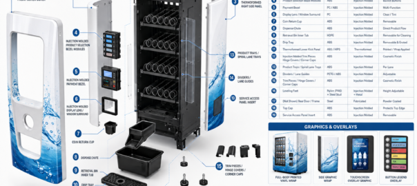
Typical thermoformed covers, injection molded functional parts and branding elements used in a beverage vending machine.

Purpose of this guide:  Provide a practical roadmap for companies developing or redesigning a vending machine and sourcing its mechanical, plastic, electronic, payment, refrigeration and graphic components in the United States.


1. Vending Machines: Plastics in Action

A vending machine is a compact automated retail system that combines mechanical structures, electronics, payment hardware, product handling, thermal management and a customer interface. The original article correctly identifies injection molded plastics, thermoformed plastics and fiberglass as important material families; this expanded guide places those materials within the complete product architecture and sourcing process.

Reference machines illustrate two common industrial-design directions: a graphic-wrapped cabinet and a sculpted, appliance-style enclosure.

Outer cabinet and structural frame

Protects the machine and carries doors, shelves, cooling equipment and internal modules. Sheet metal is common for the structural chassis; thermoformed ABS/HIPS or fiberglass can be used as exterior skins, side panels, canopies and branded surrounds.

Front door and user interface

The main customer touchpoint. Typical plastic parts include thermoformed fascia panels, injection molded bezels, payment-module housings, display surrounds, keypad frames, trim pieces and product-retrieval door components.

Payment system

Accepts cards, mobile payments, bills or coins. Use dedicated commercial payment modules; plastic housings, bezels and chutes can be custom molded around those modules.

Product storage

Shelves, trays, lane dividers, spirals, pushers and guides hold and organize products. Geometry must match the product envelope and dispensing method.

Dispensing mechanism

Motors, gearboxes, spirals, pushers, gates and drop chutes move the selected item from storage to the retrieval area.

Cooling and insulation

Refrigerated machines typically use a compressor/condenser/evaporator system, airflow ducts, insulation, gaskets and an inner liner. Molded ducts and thermoformed liners simplify airflow management and cleaning.

Electronics housing

Contains the controller, power supply, communication hardware, sensors and wiring. Molded casings and protective covers help isolate electronics and create serviceable modules.

Graphics and branding

Full-body vinyl wraps, printed inserts, screen-printed overlays, backlit graphics, decals, safety labels and product-selection legends create the customer-facing brand and operating instructions.

How the Machine Operates

  1. Customer selects a product through buttons or a touchscreen.
  2. Payment hardware validates the transaction and communicates authorization to the machine controller.
  3. The controller identifies the selected lane and activates the corresponding motor, pusher, gate or other dispensing actuator.
  4. The product is released from the storage lane and guided toward the delivery area.
  5. Sensors can confirm vend completion, product drop, door position and other conditions.
  6. The retrieval bin or door provides customer access while preventing unauthorized reach into the product compartment.
  7. For refrigerated units, the thermal-management system maintains the programmed temperature range while fans distribute conditioned air.

2. How to Design a Vending Machine

The most reliable approach is to design the machine as a platform made of serviceable modules rather than as one large assembly. Freeze the product and business requirements first; then design the cabinet, dispensing architecture, user interface and sourcing package around them.

1. Define the product and operating environment

Specify what will be sold, package dimensions, weight, fragility, temperature requirements, number of SKUs, capacity, indoor/outdoor location, ambient temperature, moisture exposure, vandal resistance, cleaning requirements and target machine life.

2. Set the commercial requirements

Define target unit cost, expected annual volume, prototype quantity, service model, payment methods, telemetry requirements, branding strategy and installation constraints.

3. Create the system architecture

Break the machine into cabinet/frame, door/UI, payment, product-storage module, dispensing mechanism, retrieval system, refrigeration/airflow, controls/electrical, graphics and service-access modules. Assign interfaces between modules early.

4. Choose the dispensing method

Use spirals for many packaged snacks, pushers/gates for bottles or cans, conveyor/elevator systems for fragile products, lockers for controlled access, or custom mechanisms for nonstandard goods. Prototype this subsystem before finalizing the cabinet.

5. Develop industrial design and ergonomics

Create the customer-facing shape, screen/button locations, product visibility, retrieval-door position and service-door access. Plan graphic zones at the same time as panel geometry.

6. Select materials and processes using DFM

Use sheet metal for load-bearing chassis members; thermoforming for large exterior skins and liners; injection molding for precise high-repeat functional parts; clear PC/PETG for windows; elastomers for seals; and printed films/vinyl for graphics.

7. Design electronics and software

Specify controller architecture, motor drivers, sensors, power supply, touchscreen or buttons, communications, payment interface, firmware, remote telemetry, diagnostics and fail-safe behavior.

8. Engineer thermal management where required

Size refrigeration hardware from heat load, product pull-down requirements, door openings, insulation and ambient conditions. Design ducts and fan paths so air reaches all product zones without excessive frost or hot spots.

9. Design for serviceability

Use modular shelves, accessible fasteners, keyed connectors, removable drip/retrieval trays, replaceable payment modules, diagnostic access and service panels. A machine that is easy to repair has lower lifecycle cost even if the initial BOM is slightly higher.

10. Prototype, test, pilot and release

Build mechanism prototypes first, then an engineering prototype, then a design-validation build and a pilot run. Close failures before committing to high-cost production tooling.

Design rule:  Do not release expensive injection molds until the product envelope, interfaces, critical dimensions and dispensing mechanism have passed prototype testing. Thermoformed panels are often easier and less expensive to revise during early industrial-design iterations.


Material and Process Selection for the Plastic BOM

Typical Part Preferred Process Common Materials Why
Large front/side skins, canopy, kick panel Thermoforming ABS, HIPS, PC/ABS Large surface area, lower tooling cost than injection molding, easy to trim and decorate.
Inner liner, airflow duct, service cover Thermoforming ABS, HIPS, HDPE, PETG Good for large shallow or moderately deep shells; easy cleaning and low part count.
Payment bezel, button housing, trim Injection molding ABS, PC/ABS, PC Tight details, snap fits, bosses, repeatable appearance.
Product tray, lane divider, pusher Injection molding ABS, PP, POM, nylon Precision features, wear resistance and repeatable fit.
Retrieval bin / chute Injection molding or thermoforming HDPE, ABS, PP Impact resistance and cleanable geometry.
Clear display/product window Thermoforming / fabrication PC, PETG, acrylic Transparency, impact resistance and formed geometry.
Gaskets, bumpers, seals Elastomer molding / extrusion TPE, EPDM, silicone Sealing, vibration isolation and soft-touch functions.
Graphics / overlays Digital print, screen print, laminate Vinyl, PET, polycarbonate film Branding, labels, touchscreen/button legends and wear surfaces.

3. Build the Bill of Materials Before You Source

A sourcing program works best when every purchased item is assigned a part number, revision, drawing/model, process, material, finish, expected annual usage and quality requirement. The BOM should distinguish custom-to-print components from commercially available modules.

BOM Category Where to Source Key RFQ Information
Structural frame / cabinet Sheet-metal fabrication Laser cut/punch, bend, weld, powder coat; confirm gauge, tolerances and grounding points.
Door frame, hinges, latch, locks Fabrication + commercial hardware Specify cycle life, security level, service access, and replacement key/lock strategy.
Thermoformed exterior panels Custom thermoformer Provide CAD, material, texture/color, wall thickness, trim datum, inserts and graphic requirements.
Injection molded trays / housings / bezels Custom injection molder Provide resin grade, texture, color, draft, critical dimensions, cosmetic zones, tool ownership and annual volume.
Dispensing spirals / pushers / motors OEM component supplier or custom mechanism supplier Match torque, speed, lane pitch, product size, motor voltage and control interface.
Payment hardware Established vending/payment OEM Select card/mobile/bill/coin options, communication interface, certifications, telemetry and field service.
Controller / I/O electronics Electronics OEM/ODM or contract manufacturer Specify I/O count, motor channels, sensors, payment interface, firmware ownership and update method.
Touchscreen / display Industrial display supplier Specify brightness, operating temperature, touch technology, glass/cover lens, connector and mounting.
Refrigeration deck Commercial refrigeration supplier Specify cooling capacity, refrigerant, voltage, airflow, ambient range, serviceability and regulatory requirements.
Fans, ducts and filters Fan OEM + plastic fabricator/molder Select airflow/static pressure, acoustics, life, ingress protection and cleanability.
Glass / transparent window Glass or polycarbonate fabricator Specify safety treatment, tint, heater/anti-fog requirement and mounting method.
Wire harnesses Cable/harness contract manufacturer Provide schematic, wire gauge, connectors, labels, test requirements and UL-recognized components as applicable.
Fasteners / inserts Industrial distributor Standardize sizes and reduce unique hardware; specify captive hardware where service access is frequent.
Graphics / overlays / labels Industrial graphics converter Supply artwork files, color targets, laminate, adhesive, UV exposure, cleaning chemicals and expected life.
Packaging Packaging supplier Engineer pallet/carton/foam protection around finished machine weight, freight mode and installation method.

4. How to Find Vending-Machine Suppliers in the USA

Start with capability-based sourcing rather than searching only for “vending machine supplier.” Many of the best sources will be specialists in a process or subsystem—thermoforming, injection molding, sheet metal, refrigeration, payment hardware, electronics, displays, wire harnesses or industrial graphics.

Industrial supplier directories

Use Thomasnet to search by process, material, location and certifications. Search terms should be specific—for example “heavy gauge ABS thermoforming Michigan,” “custom injection molded ABS housings,” “sheet metal enclosure fabrication,” “wire harness contract manufacturer” or “industrial graphics overlays.”

Industry associations and directories

Use PMMI directories to identify machinery/component suppliers, agents and distributors. For unattended retail, also use vending-industry associations, trade shows and exhibitor lists to identify payment, telemetry, refrigeration and dispensing specialists.

Trade shows

Build a supplier list from vending, convenience retail, foodservice, packaging, plastics, automation and electronics shows. Meet engineering and sales teams in person and bring a one-page sourcing brief with the BOM categories you need.

Regional manufacturing networks

Search state manufacturing associations, economic development manufacturing directories, local tool-and-die networks and regional contract manufacturers. Regional suppliers can reduce freight and make engineering changes easier during development.

Supplier referrals

Ask each selected supplier which adjacent processes they routinely integrate. A thermoformer may know graphics converters and CNC trimmers; an injection molder may know toolmakers and resin suppliers; a sheet-metal fabricator may know powder coaters and harness shops.

Existing component ecosystems

For payment, refrigeration, locks, displays, motors and controllers, prefer established commercial modules when they satisfy the requirements. Custom-design only the interfaces and parts that create differentiation.

Useful sourcing shortcut:  For custom plastic parts, issue the RFQ to a supplier that can support design-for-manufacturability, tooling, molding/forming, secondary trimming, decorating and assembly. Fewer handoffs can reduce tolerance-stack and accountability problems.


Recommended U.S. Search Resources

Thomasnet Supplier Discovery: https://www.thomasnet.com/suppliers — Search and filter North American industrial suppliers by capability, geography and certification.

Thomasnet Plastic Thermoforming: https://www.thomasnet.com/suppliers/usa/plastic-thermoforming-61020202 — Useful starting point for U.S. thermoforming sources and material/process capability comparisons.

PMMI Sales Agent Directory: https://www.pmmi.org/sales-agent-directory — Useful for finding machinery/component sales agents and distributors serving processing and packaging markets.

NSF Food Equipment Standards: https://www.nsf.org — Review food-equipment sanitation requirements when vending food or beverages.

U.S. Access Board / ADA Guides: https://www.access-board.gov/ada/guides/ — Use accessibility guidance when locating controls and other operable elements.

5. The RFQ and Supplier-Qualification Process

A good RFQ gives suppliers enough technical and commercial information to quote the same scope. Avoid sending only a rendering or a photo. Build a controlled data package so quotes are comparable.

RFQ Package Checklist

  • 3D CAD file (STEP preferred for neutral exchange) and controlled 2D drawing for critical dimensions and notes.
  • Part number and revision level.
  • Material specification, resin grade or approved alternatives; color and UV/flame/food-contact requirements if applicable.
  • Cosmetic surface requirements, texture, gloss, grain direction and designated Class-A surfaces.
  • Expected annual volume, economic order quantity, prototype quantity and forecast ramp.
  • Process assumptions: injection molding, thermoforming, CNC trimming, insert molding, printing, assembly, etc.
  • Tooling responsibility: tool type, expected tool life, ownership, storage, maintenance and end-of-life disposition.
  • Quality requirements: first article, dimensional report, capability on critical characteristics, incoming inspection and change-control expectations.
  • Packaging and delivery location.
  • Target timing for prototype, tool completion, first articles and production approval.

Evaluate Suppliers on More Than Unit Price

Supplier Evaluation Factor Example Weight
Technical fit / DFM support 20%
Quality system and process control 15%
Tooling capability and maintenance 15%
Unit price at forecast volumes 15%
Lead time and capacity 10%
Prototype / engineering-change responsiveness 10%
Secondary operations and assembly 5%
Location, logistics and inventory support 5%
Financial/business continuity risk 5%

Questions to Ask a Plastic Molder or Thermoformer

  • Can you review the CAD for draft, undercuts, wall thickness, ribs/bosses, radii and trimming strategy before tooling is released?
  • What maximum part size, draw depth, clamp tonnage and material thickness can your equipment handle?
  • Which engineering resins do you process regularly, and how do you control lot/color changes?
  • Do you build tooling in-house or manage an external toolmaker? Who owns the tool and CAD?
  • Can you provide CNC trimming, drilling, inserts, bonding, painting, screen printing, labels, graphics or subassembly?
  • How are first articles measured and approved? Can you provide dimensional reports and material certifications?
  • What is the expected prototype and production lead time, and what production capacity is available at the forecast volume?
  • How are engineering changes controlled after tool release?

6. Design Compliance Into the Machine Early

Requirements depend on the machine type, products sold, installation site and jurisdiction. Treat the following as design inputs to verify with the relevant certification body, customer and authority having jurisdiction—not as a substitute for a formal compliance review.

Food and beverage sanitation

NSF/ANSI 25 covers vending machines for food and beverages. If the machine handles food or beverages, review sanitation, cleanability, materials and construction requirements early so the mechanical design does not need major changes after tooling.

Accessibility

ADA guidance places accessible operable parts within defined reach ranges. For unobstructed adult reach, 15 to 48 inches is a key design range, and operating force is generally limited to 5 lbf for covered operable parts. Confirm the exact requirements applicable to the installation and machine configuration.

Electrical safety and certification

Plan for the applicable U.S. electrical safety listing/certification requirements with the selected NRTL and component suppliers. Use recognized components where appropriate and maintain spacing, grounding, wiring, overcurrent protection and service-access requirements in the design.

Payment and data security

Use payment hardware and software from established payment vendors and follow the applicable payment-security and network requirements. Avoid placing raw card data handling inside custom machine software unless the architecture and compliance program specifically supports it.

Outdoor operation

If installed outdoors, design for rain, UV exposure, temperature extremes, condensation, corrosion, drainage, gasket compression and vandal resistance. Specify the environmental rating required for electrical enclosures and exposed modules.

7. Recommended Development and Sourcing Sequence

  1. Freeze product envelope, capacity, environment and target cost.
  2. Prototype and prove the dispensing mechanism using representative products.
  3. Create system architecture and preliminary BOM.
  4. Package commercial modules: payment, controller, display, refrigeration, motors and sensors.
  5. Develop industrial design and split large exterior surfaces into manufacturable thermoformed/fabricated panels.
  6. Complete DFM with plastic, metal and tool suppliers before final detailing.
  7. Build an engineering prototype and perform functional, serviceability, thermal, electrical and abuse testing.
  8. Update the drawings/BOM; issue production RFQs to at least two qualified suppliers for critical categories.
  9. Release long-lead production tooling only after design validation.
  10. Build pilot units using production-intent suppliers and processes; close quality and assembly issues.
  11. Finalize work instructions, inspection plan, service documentation, spare-parts list and supplier quality agreements.
  12. Launch production with controlled revisions and an engineering-change process.
Make-or-buy principle:  Buy mature commodity modules; custom-engineer the parts that create the machine’s differentiation. The highest-value custom work is usually the industrial design, product-handling geometry, molded housings/panels, interface brackets, software integration and branding.


8. Where Om Raj Tech Fits Into the Vending-Machine Supply Chain

For OEMs developing vending machines, kiosks and other self-service equipment, Om Raj Tech can be engaged as a U.S. sourcing and manufacturing contact for custom plastic components, particularly parts suited to plastic injection molding and thermoforming. These processes cover many of the visible and functional parts highlighted throughout this guide.

Potential Vending-Machine Plastic Opportunities

  • Thermoformed front fascias, door skins, side panels, top canopies and kick panels.
  • Thermoformed inner liners, display surrounds, airflow ducts and service covers.
  • Injection molded payment bezels, touchscreen surrounds and button modules.
  • Injection molded product trays, lane dividers, pushers, guides and chutes.
  • Retrieval-bin components, hinge covers, corner caps, trim pieces and protective housings.
  • Plastic components designed to accept printed vinyl wraps, decals, labels and branded overlays.

Example plastic component families and graphics/overlay opportunities for vending-machine programs.

DEVELOPING OR RESHORING A VENDING-MACHINE PLASTIC PART?

Plastic Injection Molding • Thermoforming • Michigan

www.omrajtech.com   |   Call 248 843 9478

Source Notes

This guide expands the user-supplied article “The Anatomy of a Vending Machine: Plastics in Action.” Additional public references used for U.S. sourcing and design considerations:

Disclaimer: Material choices, compliance requirements, part geometry and sourcing decisions depend on the exact machine, product, environment and production volume. Final engineering and certification decisions should be verified by qualified engineering, certification and supplier teams.

Domestic Manufacturing Drives Innovation at MODEX 2026 – How Om Raj Tech Powers the U.S. Plastic Supply Chain

1.MODEX2026: The Pulse of U.S. Plastics Innovation

The Atlanta-based MODEX show is the premier showcase for logistics, automation, and industrial manufacturing solutions. In 2026 it highlighted a new wave of U.S.–made plastic products that are:

Focus What It Means
Reusability & Sustainability HDPE, PP, and engineering plastics engineered for closed-loop use.
Automation Compatibility Parts designed to fit conveyor, robotic, and AI-driven warehouses.
Speed-to-Market On-site tooling and rapid prototyping shorten lead times from weeks to days.

Key exhibitors Orbis Corporation, Akro-Mils, SSISchäfer USA, Monoflo International demonstrated that domestic manufacturers can deliver the same high performance as overseas competitors while offering tighter quality control and faster turnaround.

2.Why Domestic Manufacturing Matters

Benefit Why It Helps the Industry
Supply-Chain Resilience Reduces dependency on long-haul shipping, mitigating geopolitical or pandemic disruptions.
Reduced Lead Times In-country tooling and rapid injection molding enable faster prototype-to-production cycles.
Higher Quality Control ISO-certified processes and real-time inspection keep defect rates low.
Sustainability Credentials Reusable containers, recyclable plastics, and local production lower the carbon footprint.
Customization & Flexibility Small-batch, CAD-based design changes are handled in-house without long lead times.

These advantages translate directly into cost savings, higher reliability for end users, and a competitive edge for U.S. brands that demand “Made in USA” integrity.

3.OmRaj Tech – Your One-Stop Domestic Partner

Capability What We Deliver
Custom Plastic Parts Precision injection-molded ABS, PP, HDPE, and engineering plastics tailored to exact specifications.
Full Conveyor Systems Belt conveyors, roller systems, modular units all engineered for robotics and AI integration.
Material Expertise Selection of the right plastic (e.g., high-impact polystyrene, nylon, altem) for durability and performance.
End-to-End Service Consultation → CAD design → Tooling → Manufacturing → Delivery & support.
Domestic Flexibility 16 presses (110T–1100T), on-site secondary services (insert molding, sonic welding, kitting).

We partner with the same industry leaders that showcased at MODEX Orbis, Akro-Mils, SSISchäfer, Monoflo International to bring their high-volume solutions into our Michigan facility. This synergy allows us to:

  • Accelerate product launches by leveraging existing tooling and proven processes.
  • Offer seamless integration with the latest warehouse automation platforms.
  • Guarantee consistent quality through ISO certification and rigorous QA checks.

4.Impact on the U.S. Plastic Landscape

Industry Need How OmRaj Tech Helps
Automated Warehouses Custom conveyor components that fit robotics, reducing manual handling.
Food & Retail Distribution Reusable HDPE containers and pallets engineered for repeated use and easy cleaning.
Industrial Machinery Precision parts (rollers, housings) that meet stringent load and temperature requirements.
Sustainability Goals Closed-loop recycling options and low-VOC materials to satisfy corporate ESG targets.

By keeping production local, we cut shipping costs, shorten lead times, and maintain a high degree of customization exactly the capabilities highlighted at MODEX2026.

5.Take Action – Partner With Us

Whether you need a single prototype or a full-line production run, OmRaj Tech’s domestic manufacturing portfolio is ready to meet your demands. Contact us today to discuss how we can help bring your next plastic solution from concept to market faster, more sustainably, and with the reliability that only U.S. manufacturing can provide.

OmRaj Tech – Delivering Precision Plastic Solutions Right Here in Michigan.


NeoCon 2026: The New Landscape for Furniture & Why a Domestic Partner Matters

The Chicago-based NeoCon2026 show was a clear sign that the furniture industry is moving toward three intertwined imperatives: sustainability, performance, and speed to market. Large-scale commercial brands such as Global Furniture Group, Davis Furniture, Emeco, Enwork, and Herman Miller are pushing the envelope with recycled materials, high-performance composites, and modular designs that can be reconfigured on demand.

For product developers in this space, the challenge is not only to design better furniture but also to manufacture it locally to keep lead times short, reduce inventory costs, and maintain tight control over quality. That’s where a domestic manufacturing partner that brings advanced tooling and material expertise can make all the difference.

  1. What Modern Furniture Demands

Trend Why It Matters
Recyclable & low-VOC plastics Meets corporate sustainability goals and regulatory requirements.
High-strength composites (fiberglass, Kydex) Provides weight savings without compromising durability in ergonomic chairs or conference tables.
Custom surface finishes (chrome film, decorative films) Adds premium aesthetics to office seating and hospitality furnishings.
Integrated assembly features (fasteners, storage solutions) Reduces end-user assembly time and improves product reliability.

The key takeaway from NeoCon 2026 is that furniture manufacturers are looking for a single partner who can deliver both the material performance they need and the speed of production that global supply chains struggle to provide.

  1. Vacuum Forming & Composite Compression Molding – The Core of Domestic Capability

Vacuum forming remains the workhorse for producing lightweight, complex-shaped parts think chair backs, tabletops, or decorative panels.A domestic partner can offer:

  • A wide material palette: black ABS with pre-applied textured finishes (no extra surface processing needed), acrylic, PETG, polycarbonate, high-impact polystyrene, polyethylene TPO, nylon, and altem allowing designers to choose the best fit for performance or sustainability goals.
  • Integrated secondary assembly: adding rotolock fasteners inside parts or applying decorative films on the fly reduces downstream handling and speeds up time-to-delivery.
  • Support for both opaque and clear plastics, giving designers flexibility in aesthetics and function.

When a design calls for extra strength, twin-sheet vacuum forming creates hollow, rigid parts that can be welded together an approach that delivers structural integrity without the weight penalty of solid panels. Composite compression molding takes this further by reinforcing sections with fiberglass or other composites, ideal for high-stress areas such as chair seat frames or conference table edges.

These processes require complex tooling and precise process controls, but a partner that owns 16 presses ranging from 110T to 1100T can scale from prototypes to high-volume runs while keeping costs predictable.

  1. Why Domestic Production Is the Smart Choice

  • Lead-time agility – With manufacturing on Michigan soil, a design change can be incorporated into the next production run in weeks instead of months.
  • Supply-chain resilience – The ability to transfer tooling from overseas or onshore and shift capacity between facilities mitigates geopolitical risks.
  • Quality control – ISO-certified processes, on-site assembly, and real-time inspection mean that every part meets the stringent tolerances demanded by ergonomic chairs or medical-grade furniture.

For furniture companies that want to maintain a lean inventory while still offering rapid customization, these benefits translate into lower carrying costs and higher customer satisfaction.

  1. A Case in Point: How One Partner Supports Domestic Furniture Production

A Michigan-based manufacturer partnered with Formed Solutions Inc. demonstrates how vacuum forming and composite compression molding can be leveraged across a range of furniture applications:

  • Complex functional parts such as steering column covers for fire trucks illustrate the ability to produce durable, highly detailed components.
  • Decorative modules, like pontoon boat docking lights finished with chrome film, show how high-quality ClassA finishes can be achieved in a single manufacturing step.
  • Multi-material assemblies combining rigid fiberglass cores with flexible nylon or altem skins provide both strength and aesthetic appeal for office seating and conference tables.

In addition to the core forming processes, the partner offers secondary services such as insert molding, sonic welding, assembly, decoration, and kitting. This end-to-end capability means that a furniture design can move from concept directly into production with minimal handoff.

  1. Bottom Line

NeoCon2026 reaffirmed that innovation in materials is inseparable from innovation in manufacturing. For furniture brands looking to stay ahead, the next step is not just to design better products but also to choose a domestic partner who can deliver those designs quickly, reliably, and sustainably.

By combining advanced vacuum forming, composite compression molding, and on-site assembly while keeping tooling flexible and quality rigorous a local manufacturing partner can bridge the gap between concept and customer. The result?Furniture that meets modern performance standards, looks premium, and arrives faster than ever before.


Sales-procurement-engg-and-management

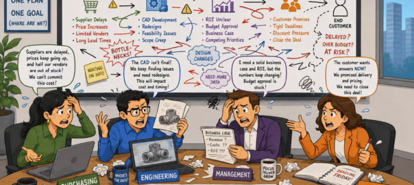
Behind One Purchase Order: The 4-Way Battle Nobody Talks About

A purchase order isn’t just a piece of paper or a line on an invoice – it’s the result of a secret negotiation happening inside every buyer’s organization. When you send a PO to a supplier, you’re not talking to one person; you’re aligning four very different perspectives:

Stakeholder What they care about How we help
Procurement Cost, lead-time, risk, compliance Flexible tooling and piece price that cuts set-up costs and shortens cycle times
Engineering Design intent, material performance, quality Material expertise in ABS, nylon, PETG, polycarbonate, fiberglass, plus design-for-manufacturing support
Management ROI, risk mitigation, strategic fit Demonstrated cost savings from domestic production and low-volume flexibility; clear return-on-investment data
Sales Customer relationship, negotiation, win-rate Early capture of constraints, collaborative solution building, and a single point of contact for all parties
  1. Procurement – The Cost & Risk Champion

Procurement’s mandate is to keep the company’s wallet healthy while ensuring a reliable supply chain. In our world of injection molding, thermoforming, and fiberglass composites, that means:

  • Tooling Flexibility – We offer “mud-based” tooling (a shared frame with interchangeable inserts) so you can run up to four different parts on one mold. This keeps tool costs down when volumes are low or change frequently(1).
  • Hybrid Production – Most of our work is done through a hybrid model: a local domestic tool shop partners with overseas manufacturers to keep lead-times short and quality high, which protects you against global supply disruptions(1).
  1. Engineering – The Design & Quality Guardian

Engineering wants parts that meet specifications without unnecessary cost or delay. We provide:

  • Material Breadth – From black ABS for rugged automotive components to PETG and polycarbonate for medical devices, our vacuum-forming line (used in furniture, industrial and medical markets) can produce high-finish parts with the right mechanical properties(3).
  • Composite Strength – For applications that need more than a single plastic layer, we use composite compression molding (fiberglass + resin transfer) to deliver hollow, rigid parts with weld-strength where needed(3).
  1. Management – The ROI & Strategy Officer

Management looks at the bigger picture: does this partnership make financial sense? Does it align with our long-term goals?

  • Cost-Effective Production – By leveraging low-volume tooling and domestic production, we keep per-unit costs competitive while shortening delivery windows. This translates into lower inventory carrying costs for your organization(2).
  • Risk Mitigation – Our hybrid model and local tool shops mean you’re not locked into a single overseas supplier; if something happens in one region, the other can step in.
  1. Sales – The Bridge Builder

Sales often thinks of themselves as the “convincer” – but winning a PO is about aligning all four voices. Here’s how we do it:

  1. Ask Early About Constraints – Talk to procurement first to understand cost ceilings and lead-time limits.
  2. Show Engineering Options – Present material choices, tooling flexibility (mud-based or hybrid), and any secondary operations (e.g., sonic welding, kitting) that can add value(1).
  3. Translate ROI for Management – Provide clear data on how our solutions reduce inventory, lower tooling costs, and shorten time-to-market(2).
  4. Close with a Unified Offer – Present a single, coherent proposal that satisfies all stakeholders, making the PO an internal compromise rather than a battle.

The Real Job of Sales: Negotiating into Existence

Every order is not won outright; it’s negotiated into existence. A purchase order is only “signed” once procurement, engineering, management, and sales have agreed on:

  • Price that fits the budget
  • Lead-time that matches production schedules
  • Quality that meets design tolerances
  • Risk that aligns with strategic objectives

When all four parties speak the same language—thanks to our injection molding, thermoforming, and fiberglass expertise—you’ll see a higher win rate and smoother project execution.

Takeaway

A purchase order is more than a transaction; it’s an internal compromise. By understanding what each stakeholder cares about and using our versatile manufacturing capabilities to meet those needs, you can turn the four-way battle into a single, aligned decision. Let’s build that bridge together—because when procurement, engineering, management, and sales walk side by side, every PO becomes a win for everyone involved.

prototype thermoforming

Thermoformed Plastics Design Requirements: Specifications and Metrics

Designing thermoformed plastic parts requires strict adherence to geometric, material, and thermal specifications to ensure manufacturability and performance.

  1. Geometric Design for Thermoforming (DFT)
Design Element Specification/Metric Constraint & Rationale
Radii (Internal Corners) Minimum radius: 1.5 mm. Larger radii (e.g., 0.125″ minimum for structural parts) are critical to minimize stress concentrations and material thinning.
Tool/Material Radius Ratio Radius minimum should be equal to or greater than the initial material thickness. If the radius is smaller than the starting thickness, forming is difficult or impossible.
Draft Angles (General) Generally recommended: >2°. Ensures easy demolding without surface defects.
Draft Angles (Molds) Negative molds: 1.5° – 2° standard. Positive molds: 4° – 6° recommended. Facilitates clean tool release and improves reproducibility.
Rib Draft Angle Minimum draft: . Essential for part removal and uniform material distribution.
Rib Base Radii Minimum: 25% of the material’s thickness. Example: For a 0.250″ gauge, apply a minimum base radius of 0.0625″.
Forming Ratio (Negative) Depth-to-Width Ratio should not exceed 1.5:1. Higher ratios result in significant thinning, increasing the risk of rupture at the bottom edges.
Wall Thickness The original sheet thickness is the maximum wall dimension. The deepest drawn areas will inherently be the thinnest.
Tolerance (Typical) General formed features: +/- 0.060″. Tighter tolerances (e.g., +/- 0.010″) require additional, costly operations.
Shrinkage (PC) Polycarbonate mold shrinkage: 0.005 – 0.007″ per inch (0.13-0.18 mm). Shrinkage in the extrusion direction (MD) for 1.80-2.30 mm sheet is typically 6-7%, while transverse direction (TD) shrinkage is 0.5%.


  1. Processing and Temperature Specifications (Polycarbonate Example)
Process Step Temperature/Time Specification Critical Requirement
Pre-Drying (PC Sheet) 250°F (121°C) in an air circulating oven. Must occur before thermoforming to prevent moisture vaporization (air bubbles/voids).
Drying Time (PC Example) 0.236″ (6mm) gauge sheet requires 24 hours at 250°F (121°C). Sheets stacked without air spacing will not dry.
PC Softening Point Glass transition temperature is 298°F (148°C). Softening begins rapidly above 311°F(155°C).
Sheet Forming Temp (PC) Target range: 340°F to 415°F (171°C−213°C)

Optimum: 350°F−375°F (177°C−191°C)

Polycarbonate has a relatively narrow forming temperature range.
Mold Temperature (PC) Recommended mold temperature range: 210°F−250 °F (99°C−121°C) A heated mold ensures better shaping, more gradual cooling, and reduced induced stress.


III. Material and Compliance Requirements

Requirement Specification/Metric Relevant Materials & Example
UV Resistance Required for exterior parts (e.g., consoles, housings). ASA offers excellent UV stability. ABS is highly UV sensitive and requires a UV cap layer (e.g., ASA) for outdoor service.
Heat Tolerance (Low) Insufficient HDT leads to permanent deformation. PVC/Acrylic blends have a low heat distortion point, around 71°C (160°F). HDPE melting point is typically 120°C to 135°C.
Flammability Rating Minimum for enclosed interiors/electrical housings: UL 94 V-0. V-0 requires burning to stop within 10 seconds on a vertical specimen, with no flaming drips. V-2 explicitly permits flaming drips.
Fire Testing Component subjected to flame for 2 1/2 minutes. Temperature within one inch of the component must reach at least 648°C during the test.
Environmental Stress Crack Resistance (ESCR) Must be specified for structural polyolefins (HDPE) near chemicals. HDPE standard grades are susceptible to brittle failure when stressed and exposed to surface-active agents (fuels, cleaners).
Chemical Encasing (Tanks) Cellular plastic must not change volume by more than 5% or dissolve after 24 hours at 29°C in reference liquids. Non-polyurethane encasing plastic must have compressive strength of at least 60 pounds per square inch at 10% deflection.
Thermal Expansion PC thermal expansion rate is approximately four times higher than metal. For fastening to metal, slotted holes and controlled torque are mandatory to prevent thermal strain failure.


Comparing ISO 9001 and ISO 13485 Quality Management Standards


The more general quality standard ISO 9001 serves as a major foundation for ISO 13485, the globally recognized quality management system (QMS) standard for the medical device sector. While maintaining quality and efficacy is their shared objective, ISO 13485 has important additions and revisions that are specifically designed to fulfill regulatory criteria pertaining to medical device performance and safety.

Section 1: Parallels In between the Standards
Both ISO 9001 and ISO 13485 use a similar basic framework and provide requirements for an all-encompassing Quality Management System (QMS).

Foundations of Shared QMS ISO 9001:2015 vs. ISO 13485:2016
Process Approach The foundation of both standards is a process approach to quality control.
Management Responsibilities Both call for top management’s dedication to the QMS, which includes setting the quality targets and policy.
QMS Planning In order to achieve quality goals, both require planning that considers the integrity of the QMS during the planning and execution of improvements.
Resource Management Both need identifying and supplying resources, such as human resources (competence, training, and awareness) and infrastructure (e.g., facilities, process equipment).
Operation/Realization Both contain customer-related procedures, design and development (Section 7.3 in 13485; Section 8.3 in 9001), and management of externally supplied goods and services (buying) are all covered in detail in both.
Improvement Both emphasize measurement, analysis, and improvement processes, including mandatory requirements for implementing corrective action (CA) to prevent the recurrence of nonconformities.

Part 2: Important Distinctions and ISO 13485 Details

A sector-specific standard called ISO 13485 was created for businesses engaged in one or more phases of a medical device’s life cycle. In contrast to ISO 9001, which places a strong emphasis on improving customer satisfaction and continual development, ISO 13485 places a higher priority on the legal standards necessary for performance and safety.

ISO 13485 Specific Requirements Key Focus Corresponding ISO 9001 Clause Status
Regulatory Requirements The organization must identify its role(s) under applicable regulatory requirements and incorporate these into the QMS. Compliance is the primary goal. ISO 9001 focuses on statutory/regulatory compliance but lacks the specific emphasis on medical device safety regulations.
Risk Management Requires the application of a risk-based approach to control appropriate QMS processes. The term “risk” specifically pertains to the safety or performance requirements of the medical device. ISO 9001 applies general risk-based thinking to address risks and opportunities.
Documentation & Records Requires the establishment and maintenance of one or more Medical Device Files for each device type or family, including general descriptions, specifications, manufacturing, packaging, and servicing procedures. Confidential health information protection is also required. ISO 9001 requires documented information and records but has no equivalent clause for the Medical Device File.
Record Retention Records must be retained for at least the lifetime of the medical device (as defined by the organization), but not less than two years from the device release. ISO 9001 generally requires retaining documented information to support the operation of processes.
Outsourced Processes Requires specific controls for outsourced processes, including written quality agreements, with controls proportionate to the risk involved. ISO 9001 addresses external provision but does not explicitly require a written quality agreement.
Special Processes Contains clauses with no equivalent in ISO 9001:2015, such as requirements for the cleanliness of product (7.5.2), installation activities (7.5.3), servicing activities (7.5.4), and particular requirements for sterile medical devices (7.5.5, 7.5.7). These clauses contain requirements specific to the medical industry.
Post-Delivery Activities Requires documented procedures for timely complaint handling (8.2.2), reporting adverse events/issuing advisory notices to regulatory authorities (8.2.3), and defining traceability for implantable medical devices (7.5.9.2). ISO 9001 addresses customer feedback and post-delivery activities in a general sense.

Part 3: Transitioning from ISO 9001 to ISO 13485

An organization currently certified to ISO 9001 has a substantial advantage, as the fundamental QMS framework (process approach, planning, resources, infrastructure) is already in place.

The process of moving from a general ISO 9001 QMS to the specialized ISO 13485 QMS primarily involves adapting and integrating the existing system to meet the rigorous, regulatory-driven requirements of the medical device sector.

Key areas for adaptation:

  1. Define Regulatory Context: The organization must first identify and document its specific role(s) in the medical device life-cycle (e.g., manufacturer, distributor, service provider) and determine all applicable regulatory requirements specific to its activities and markets.
  2. Integrate Risk Management (Safety Focus): The existing risk approach must be reframed to focus specifically on the safety and performance of the medical device, incorporating mandated risk management activities throughout the product realization process.
  3. Enhance Documentation: Create and maintain the sector-specific documentation, most critically the Medical Device File for each device type or family. Ensure all records meet the heightened retention requirements (lifetime of the device, minimum two years).
  4. Strengthen Control of Outsourcing: Implement written quality agreements with external suppliers for outsourced processes and ensure the level of control and monitoring is proportionate to the risk presented by the purchased product.
  5. Implement Specialized Process Controls: Document and implement procedures for activities specific to medical devices, such as:
    • Validation of software used in the QMS and production.
    • Requirements for cleanliness and contamination control.
    • Procedures for installation and servicing (if applicable).
    • Specific traceability requirements, particularly for implantable devices.
  6. Develop Post-Market Procedures: Establish robust, documented procedures for handling customer feedback and mandatory complaint handling, including mechanisms for evaluating the necessity of reporting adverse events and issuing advisory notices to regulatory authorities.

ISO 13485 requires establishing, implementing, and maintaining documentation for any procedure or activity required by the standard or applicable regulatory requirements. By using the existing ISO 9001 framework injection molding, the organization builds upon its foundation by adding the necessary regulatory rigor and documented controls required for medical device quality.


Solid Works Design of Plant Tray For Injection Molding

Abstract

This report presents a comprehensive technical study on the design of a plant tray using SolidWorks with Design for Manufacturing (DFM) principles applied for injection molding. The plant tray, intended for agricultural and nursery use, requires high strength, low cost, and durability under outdoor conditions. DFM considerations such as wall thickness, draft angles, rib and boss design, ejector pin placement, gate and runner optimization, and material shrinkage are systematically discussed. Case studies highlight the impact of poor vs. optimized design on manufacturability and cost. SolidWorks workflows are detailed with step-by-step methodology. The report concludes with manufacturing efficiency analysis, cost breakdown, and recommendations for scalable mass production.

Introduction to DFM and Injection Molding

Design for Manufacturing (DFM) is an engineering methodology that ensures a product can be manufactured easily, reliably, and cost-effectively without compromising its performance or functionality. Injection molding is one of the most widely used manufacturing processes for plastic products due to its ability to produce high volumes at low per-part cost. However, without proper DFM, defects such as sink marks, warpage, weld lines, and excessive cycle times can occur. This section explores the principles of DFM, particularly in relation to injection molding. Key topics include:
– Importance of uniform wall thickness
– Draft angles for ejection
– Avoidance of sharp corners
– Gate and runner placement for balanced flow
– Structural reinforcements with ribs

DFM reduces tool complexity, minimizes production waste, and extends mold life. By applying these rules in SolidWorks during design, costly reworks and delays can be avoided.

Plant Tray Design Requirements

The plant tray serves as a multi-cavity holder for pots, commonly used in nurseries and agricultural applications. The requirements for its design include:
Strength: Must withstand the combined weight of multiple filled pots.
Durability: Must resist cracking under repeated use and UV exposure.
Drainage: Circular cutouts ensure excess water is drained efficiently.
Stackability: Trays must nest or stack for efficient storage and transport.
Lightweight construction: To reduce handling effort and shipping costs.
Manufacturability: Design should avoid undercuts, allow easy molding, and minimize cycle time.

DFM ensures these functional requirements are achieved without sacrificing ease of production.

Material Selection and Shrinkage Considerations

The choice of material is critical for performance and manufacturability. Polypropylene (PP) and High-Density Polyethylene (HDPE) are the most common choices:
Polypropylene (PP): Excellent toughness, flexibility, chemical resistance, and UV stabilizers available. Shrinkage ~1.0–1.5%.
HDPE: Higher stiffness and impact resistance, suitable for heavier loads. Shrinkage ~1.5–1.8%.

Wall Thickness and Draft Angles

Uniform wall thickness is a core principle of DFM. For this tray:
– Wall thickness = 2.0–2.5 mm
– Thin enough to cool quickly but thick enough for durability.
– Prevents sink marks and ensures dimensional stability.

Draft angles of 1.5–2° are applied on all vertical surfaces. Draft Analysis in SolidWorks confirms manufacturability.

Ribs, Bosses, and Locating Features

Ribs reinforce the tray while minimizing material use. DFM rules applied:
– Rib thickness = 0.5 × wall thickness
– Rib height = 2–3 × wall thickness
– Fillet radius at base = 0.25–0.5 × rib thickness

Bosses are used as locating and fastening features. In this tray, circular bosses also act as drainage holes. For dowel pin fits, a 10 mm pin requires 10.1–10.2 mm hole size to account for shrinkage.

Fillets, Stress Distribution, and Flow Optimization

Sharp corners are avoided to reduce stress concentrations and improve mold flow. Fillets with radii of 0.5–1 mm are added at intersections. SolidWorks simulation demonstrates smoother flow paths with fillets compared to sharp edges. Case Study: A rib-to-wall junction with no fillet caused flow hesitation and weld line formation. Adding a 0.8 mm fillet eliminated the issue.

Ejector Pin Placement and Mold Design

Ejector pins are required for demolding. Best practices include:
– Place ejector pins on non-cosmetic surfaces.
– Position at rib bases to avoid sink marks.
– Distribute evenly to prevent warping.

In the tray design, ejector pins are located under ribs and thicker regions, ensuring smooth ejection without visible marks.

Gate and Runner Placement

Balanced filling is achieved with proper gate and runner placement. For this tray:
– Edge gates at thicker ribs for smooth filling.
– Balanced runner layout ensures equal flow.

Drainage and Stackability Features

Drainage cutouts prevent waterlogging and are drafted to mold cleanly. Stackability is achieved through geometric nesting. SolidWorks assembly tests confirm trays can stack without interference.

SolidWorks Workflow – Detailed

Step-by-step modeling report in SolidWorks:

  • Concept 1
    Concept 1 is designed as per the rough sketch shared by the customer.
    For reference, two models of pot were shared to check and choose the best suitable to fit 8 pots as per the shared sketch.One model (HP5181) was selected for the tray design and it was designed as per the sketch contraption.
  • Meeting with customer for feedback
    Meeting was held for feedback from customer after submission of Concept 1 design.Weight and tray height needed reduction as per the feedback.
    Current weight of the tray was 600 grams.
    Also, thin and shallow tray design was offered to considered for design improvements.
  • Concept 2
    In phase 2 of design, competitive analyses were done from the market available plant trays.
    Weight was reduced from 600 to 130 grams by doing all the effective features like thinning and shallowing of the excess area of the tray.A meeting was held for the reviews from customer and concept 2 design was approved by the customer.

    After final approval, the design needed fine tuning and finally it was prepared for DFM by adding all the features required for injection molding as stated above.

  • Design summary 

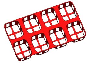
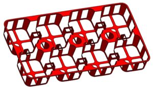
    Here shown is the plant pot, based on this model, we need to design the tray of size mentioned for 8 pots.

  1. Create base rectangle sketch for tray.
  2. Cutout sections were introduced for drainage and light weighting.
  3. Contraption done as per the layout defined by the customer.
    4. Add ribs using Rib tool with automatic draft.
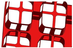

    5. Applied fillets to all internal corners.

    6. Used Shell tool to optimize weight.

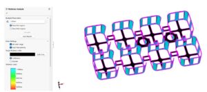
    7. Thickness Analysis ensures uniform wall distribution.

DFM Validation and Mold Flow Analysis

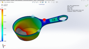
Mold flow analysis predicts material flow, cooling, and shrinkage. Simulation identifies potential weld lines, air traps, and hotspots.

Cost & Manufacturing Efficiency Analysis

DFM directly influences manufacturing cost. Factors include:
Tooling cost: Reduced by eliminating undercuts and sharp corners.
Cycle time: Lowered with uniform walls (average ~30–40s per tray).
Material usage: Optimized with ribs instead of thick walls.
Ejection efficiency: Reduced wear prolongs tool life.

Conclusion

This report demonstrates how SolidWorks and DFM principles combine to create a manufacturable, cost-effective, and durable plant tray. Through careful design of wall thickness, ribs, draft angles, fillets, and gating strategy, the tray is optimized for injection molding. Case studies validate the impact of DFM on reducing defects and costs. Future work may include automation of tray nesting and further optimization of cooling channels. DFM is not just a design practice—it is  economic advantage in high-volume production.

Essential Components and Suppliers in the Marine Industry

The marine industry is built on precision, reliability, and innovation. Whether it’s for recreational boating, commercial vessels, or luxury yachts, every component—from the smallest adhesive to the largest structural part—plays a critical role in performance and safety. Behind every successful boat builder is a network of specialized suppliers who provide the right products at the right quality.

Here are some of the most essential components and suppliers that power the marine industry:

  1. Seating and Upholstery Suppliers

Comfort and durability are key in marine seating. Specialized suppliers provide water-resistant seats, cushions, and helm chairs built with UV-stable vinyl, quick-dry foam, and corrosion-resistant hardware. Premium seating is not just about looks—it’s about ergonomics, safety, and resilience in tough marine environments.

Example of suppliers:

  •  Chestnut Ridge Foam Inc:  Specialty: High-performance foam solutions for marine seating and upholstery.


  • Wise Seats inc:  Specialty: Leading manufacturer of marine seating systems for OEMs and aftermarket.
  1. Communication & Navigation Systems

Marine communication suppliers deliver critical technologies such as VHF radios, GPS, AIS, radar, and digital switching systems. These suppliers ensure boaters stay safe and connected on the water, whether it’s a small fishing vessel or a superyacht. Partnerships with OEMs often include integrated dashboards and smart control systems.

Example:

  •  Tocaro Blue inc:  Specialty: Advanced wireless communication systems for marine vessels.


  • Icom America inc:  Specialty: Marine radios and navigation electronics.

AIS class b transponder

  1. Marine Motors & Propulsion Systems

Engines and propulsion are the heart of any boat. Suppliers in this segment provide inboard and outboard motors, electric propulsion systems, and precision propellers. From high-torque diesel engines to efficient electric drives, marine propulsion suppliers balance performance with efficiency and compliance with emissions standards.

Example: 

  • Yamaha Motor Corporation, U.S.A: Yamaha Motor Corporation is renowned for its cutting-edge marine propulsion systems

Yamaha propulsion systems for boats 

  • Hercules Electric Mobility, Inc: Specialty: Advanced electric propulsion systems for recreational and OEM marine applications.

Hercules propulsion system 

  1. Fiberglass Components (Small and Large Parts)

Fiberglass remains one of the most versatile materials in boatbuilding. Small parts like hatches, lockers, and enclosures are commonly produced using open layup methods. Large parts such as hulls, decks, and consoles are often manufactured with Resin Transfer Molding (RTM) or vacuum infusion, ensuring strength, durability, and smooth finishes. Specialized fiberglass suppliers support OEMs with corrosion-resistant, waterproof parts tailored to marine environments.

  • OmRaj Tech: Marine Focus: Supplies custom fiberglass parts for marine, agriculture, and construction sectors.
  1. Resins, Adhesives, and Sealants

Strong bonds keep vessels seaworthy. Marine adhesives and resins—epoxies, polyurethanes, and silicones—are essential for structural bonding, waterproof sealing, and vibration resistance. Suppliers in this sector focus on high-performance chemistries that withstand saltwater, UV exposure, and extreme temperatures, ensuring long-lasting reliability.

  • Allnex:  Specialty: Coating resins and additives, including VIAPAL® gelcoats and barrier coats for marine and pool applications.


  •  WEST SYSTEM : Specialty: Industry leader in marine-grade epoxy systems.


  1. Marine-Grade Plywood & Composites

Marine plywood is the foundation for interiors, bulkheads, and decks. Suppliers provide plywood treated for water resistance, dimensional stability, and rot prevention. Increasingly, builders are also turning to lightweight composite boards and laminates as alternatives, reducing weight without compromising strength.

  • Supersede:  Specialty: Creator of Supersede Marine Board, a high-performance, eco-friendly alternative to traditional marine-grade plywood.


  • Composites One:  Specialty: Distributor and manufacturer of advanced composite materials including core materials, resins, and reinforcements used in marine construction.
  1. Instrumentation & Control Systems

Instrumentation suppliers provide gauges, displays, and control panels that interpret and manage everything from engine performance to onboard electrical systems. With the rise of digital interfaces, suppliers are integrating touchscreen controls, NMEA 2000 compatibility, and smart connectivity to enhance user experience.

  • Alltek Marine Electronics Corp:  Specialty: Advanced AIS (Automatic Identification System) solutions for marine navigation and safety.


  • OceanVault: Specialty: Hardware-only marine security systems designed to protect high-value marine assets.
  1. Climate & Comfort Systems

From air conditioning and heating units to sunroofs and shading systems, comfort solutions are critical for today’s boaters. Suppliers in this area work closely with OEMs to provide integrated climate systems designed for energy efficiency and quiet operation in compact marine spaces.

  • Webasto Thermo & Comfort North America:  Specialty: Marine heating, cooling, and ventilation systems.


  • Dometic Marine:  Specialty: Complete onboard climate solutions including air conditioning, refrigeration, and ventilation.
  1. Safety & Compliance Equipment

Marine safety suppliers deliver life jackets, fire suppression systems, navigation lights, bilge pumps, and emergency beacons. These components are often regulated and certified, ensuring vessels meet strict safety standards before hitting the water.

  • Sea-Fire Marine:  Specialty: Marine fire suppression and detection systems


  • ACR Electronics:  Specialty: Emergency beacons and survival gear for marine safety.
  1. Hardware, Fasteners & Small Parts

Behind every finished boat are thousands of small but critical parts—hinges, latches, cleats, rails, and stainless-steel fasteners. Marine hardware suppliers specialize in corrosion-resistant alloys and precision manufacturing that guarantee long-term reliability, even in saltwater conditions.

  • Teak Isle Mfg. / Boat Outfitters:  Specialty: Custom marine hardware, access doors, latches, hinges, and small parts.


  • Schaefer Marine:  Specialty: Precision-engineered stainless steel marine hardware.


Top 10 Michigan Companies Exhibiting at IBEX 2025

The International Boat Builders’ Exhibition & Conference (IBEX) is the premier event for the marine industry, where innovation and craftsmanship converge. Michigan, long known for its strength in advanced manufacturing, is once again making waves at IBEX 2025. From propulsion systems to plastics and precision machining, these Michigan-based companies are shaping the future of boating.


Here are the Top 10 Michigan Companies you should visit at IBEX 2025:


  1. TREMEC – Novi, MI


Tremec.com


TREMEC is a global leader in drivetrain solutions, supplying transmissions, electric drivetrains, clutches, gears, and integrated control systems. For the marine industry, their technologies provide durability, efficiency, and smooth high-torque performance—making them a go-to partner for OEMs worldwide.


  1. Om Raj Tech – Okemos, MI


OmRajTech.com


Om Raj Tech manufactures fiberglass, thermoforming, and plastic injection molding solutions, proudly made in Michigan. With ISO-certified facilities, they serve the marine sector by producing corrosion-resistant and waterproof components such as ladder lids, bow walk doors, anchor locker lids, consoles, and custom enclosures. Their team supports customers from design and prototyping through full-scale production.


  1. Webasto – Fenton, MI


Webasto.com


A global name in climate comfort systems, Webasto equips boats with heating, cooling, chillers, sunroofs, and shading solutions. Their systems ensure onboard comfort and performance for yachts and recreational vessels alike.


  1. Caster Concepts – Albion, MI


CasterConcepts.com


Based in Albion, Caster Concepts is a leading American manufacturer of industrial casters and mobility systems. Their products reduce ergonomic injuries, increase load capacity, and minimize replacement frequency—benefits that extend to aerospace, marine, and heavy-equipment industries.


  1. ACME Marine Group – Walker, MI


AcmeMarine.com


Known for precision-engineered propellers, ACME Marine Group designs and manufactures propellers trusted by leading inboard boat brands. Made in the USA, their propellers deliver consistency and unmatched performance.


  1. Alpine Marine Audio – Auburn Hills, MI


Alpine-USA.com


Alpine is redefining marine audio with its premium line of sound systems. Designed for bold aesthetics and superior sound quality, Alpine ensures every boating trip has the perfect soundtrack.


  1. LilliPad Marine – Traverse City, MI


LilliPadMarine.com


This award-winning manufacturer is recognized for its innovative marine products, including diving boards, boarding ladders, and the Ghost Mount system. LilliPad products are designed to maximize fun and functionality on the water.


  1. Medallion Instrumentation Systems – Spring Lake, MI


MedallionIS.com


Medallion is at the forefront of marine instrumentation, offering systems that interpret, display, and control onboard functions. Their feature-rich solutions are trusted by OEMs looking for advanced yet user-friendly marine system interfaces.


  1. Multiax Technologies – Grandville, MI


MultiaxTech.com


Multiax specializes in CNC routers built for the demands of boatbuilding. With machines ranging from 5’x5’ to 20’x200’, they provide precision cutting, trimming, and machining of fiberglass hulls, decks, and aluminum structures.


  1. GLIDE Bearings & Seal Systems – Alto, MI

GlideBearings.com


GLIDE Bearings manufactures non-metallic marine bearings and dripless shaft seals. Their ULTRA Seal System has become a favorite among sport fishing and yacht manufacturers thanks to its quick-change design—no haul-out required.

Proud Sponsor of the Workforce Solutions Summit 2025

We are pleased to inform you that we are a sponsor of the Workforce Solutions Summit on September 18, 2025, in Grand Rapids, Michigan. It is a daylong conference from 8:00 AM to 4:00 PM where you’ll see manufacturing professionals, industry visionaries, and thought leaders who are dedicated to building a better workforce for the future.

As a business committed to the development of the manufacturing sector, we are all too conscious of the imperative to sponsor an event that encourages creative thinking, creates communities, and provides practical solutions to the industry’s most pressing workforce challenges today.


Why the Workforce Solutions Summit Matters

Manufacturing continues to be in a high-speed situation. Whether it is implementation of technology or absence of workers, companies are in a situation where innovation and thinking ahead are a must. One of the greatest challenges to the board is obtaining a skilled, trusted, and forward-thinking workforce.

Workforce Solutions Summit is designed to address these challenges head-on. Attendees will gain valuable insights on industry-defining trends and leave the event with practical strategies they can take back to their own organizations.

Some reasons why this summit stands out include:

  • Practical Applications: It deals with practical workforce issues and solutions.

  • Industry Experience: Global leaders in manufacturing and industry experts will present strategies and case studies.

  • Networking Time: Time to meet peers, form relationships, and swap ideas.

  • Joint Culture: Attendees will be immersed in a culture dedicated to solving shared workforce challenges.

It’s more than just learning. It’s where you can come to get energized, identify where you might find resources, where you might create some partnerships that can have a lasting effect.


Om Raj Tech at the MMA Workforce Summit – Sept 18, 2025 | Grand Rapids, MI

Om Raj Tech is proud to be part of this year’s Michigan Manufacturer’s Association Workforce Summit. As a trusted CETEC ERP integration partner and manufacturer’s representative for Michigan-based manufacturers, we help companies modernize their operations, streamline production, and strengthen supply chain visibility.

With deep expertise in ERP implementation tailored for small to mid-sized manufacturers, we enable businesses to reduce manual inefficiencies, improve real-time data access, and scale confidently. Our partnerships with Michigan plastics, thermoforming, and fiberglass manufacturers ensure we bring both technology and industry experience to every engagement.

If you’re attending the Summit, let’s connect to explore how digital tools and strong local manufacturing partnerships can drive smarter, faster, and more resilient operations.


Discounted Registration for Our Network

We are an honored sponsor and we’d be delighted to give our network a special discount. When you sign up for the event, just use the code SPONSOR25 at checkout and receive $25 off your ticket.

It is not limited in how many users can utilize it, so tell your colleagues, your customers, and any individuals in your life who might benefit from getting out.

👉 Register today at mimfg.org/workforcesummit

We can’t wait to see many familiar faces and greet many new friends in September in Grand Rapids.


Our Workforce Development Promise

Sponsoring the Workforce Solutions Summit is not just sponsorship to us—it’s our investment in the future of manufacturing. We know that this industry’s future is not just about technology and innovation but about the individuals behind it.

An effective workforce is the basis for expansion. Investment in events such as this enables a platform through which an exchange of thoughts, shared challenge fighting, and solution application are feasible. It reflects our dedication to collaboration as a method of overcoming workforce deficiencies, boosting workplace spirit, and readying the industry for tomorrow’s manufacturing leadership.


What You Can Expect at the Event

Workforce Solutions Summit includes a busy agenda with learning alongside networking possibilities. Attendees can look forward to:

  • Expert Sessions: On recruitment, retention, training, and leadership.

  • Interactive Discussions: Hands-on discussion on bridging workforce gaps.

  • Networking Breaks: Time to socialize with peers, share experiences, and establish new partnerships.

  • Actionable Resources: Materials that can be implemented within minutes.

Whether you are a business executive, human resource executive, manager, leader, or in any career related to these, the summit has something for everyone.


Event Details at a Glance

  • Date: September 18, 2025

  • Location: Grand Rapids, Michigan

  • Time: 8:00 AM – 4:00 PM

  • Discount Code: SPONSOR25


Join Us in Grand Rapids

We’d love to have you there for this momentous occasion. You’ll pick things up in a totally different way, get hands-on fixes, and mingle with people who are no less dedicated to workforce success than you are.

Don’t miss out on the opportunity to be part of a community of innovators and leaders collaborating to create the future of manufacturing. Make sure to use our special discount code SPONSOR25 at checkout to get a discount on your registration.


On the Workforce Solutions Summit

Annually organized by the Michigan Manufacturers Association (MMA), the Workforce Solutions Summit is a flagship event dedicated to finding solutions for today’s manufacturers’ workforce challenges. From finding qualified employees to structuring training programs and boosting retainability, the summit presents timely yet practical insights.

Today’s event provides a day of education, connections, and an opportunity to solidify your strategy for workforce development.

![Insert Workforce Solutions Summit Logo Here]

We are honored to be featured in the event and look forward to assisting the manufacturing community to thrive. We look forward to seeing you in Grand Rapids on September 18!