Abstract
This report presents a comprehensive technical study on the design of a plant tray using SolidWorks with Design for Manufacturing (DFM) principles applied for injection molding. The plant tray, intended for agricultural and nursery use, requires high strength, low cost, and durability under outdoor conditions. DFM considerations such as wall thickness, draft angles, rib and boss design, ejector pin placement, gate and runner optimization, and material shrinkage are systematically discussed. Case studies highlight the impact of poor vs. optimized design on manufacturability and cost. SolidWorks workflows are detailed with step-by-step methodology. The report concludes with manufacturing efficiency analysis, cost breakdown, and recommendations for scalable mass production.
Introduction to DFM and Injection Molding
Design for Manufacturing (DFM) is an engineering methodology that ensures a product can be manufactured easily, reliably, and cost-effectively without compromising its performance or functionality. Injection molding is one of the most widely used manufacturing processes for plastic products due to its ability to produce high volumes at low per-part cost. However, without proper DFM, defects such as sink marks, warpage, weld lines, and excessive cycle times can occur. This section explores the principles of DFM, particularly in relation to injection molding. Key topics include:
– Importance of uniform wall thickness
– Draft angles for ejection
– Avoidance of sharp corners
– Gate and runner placement for balanced flow
– Structural reinforcements with ribs
DFM reduces tool complexity, minimizes production waste, and extends mold life. By applying these rules in SolidWorks during design, costly reworks and delays can be avoided.
Plant Tray Design Requirements
The plant tray serves as a multi-cavity holder for pots, commonly used in nurseries and agricultural applications. The requirements for its design include:
– Strength: Must withstand the combined weight of multiple filled pots.
– Durability: Must resist cracking under repeated use and UV exposure.
– Drainage: Circular cutouts ensure excess water is drained efficiently.
– Stackability: Trays must nest or stack for efficient storage and transport.
– Lightweight construction: To reduce handling effort and shipping costs.
– Manufacturability: Design should avoid undercuts, allow easy molding, and minimize cycle time.
DFM ensures these functional requirements are achieved without sacrificing ease of production.
Material Selection and Shrinkage Considerations
The choice of material is critical for performance and manufacturability. Polypropylene (PP) and High-Density Polyethylene (HDPE) are the most common choices:
– Polypropylene (PP): Excellent toughness, flexibility, chemical resistance, and UV stabilizers available. Shrinkage ~1.0–1.5%.
– HDPE: Higher stiffness and impact resistance, suitable for heavier loads. Shrinkage ~1.5–1.8%.
Wall Thickness and Draft Angles
Uniform wall thickness is a core principle of DFM. For this tray:
– Wall thickness = 2.0–2.5 mm
– Thin enough to cool quickly but thick enough for durability.
– Prevents sink marks and ensures dimensional stability.
Draft angles of 1.5–2° are applied on all vertical surfaces. Draft Analysis in SolidWorks confirms manufacturability.
Ribs, Bosses, and Locating Features
Ribs reinforce the tray while minimizing material use. DFM rules applied:
– Rib thickness = 0.5 × wall thickness
– Rib height = 2–3 × wall thickness
– Fillet radius at base = 0.25–0.5 × rib thickness
Bosses are used as locating and fastening features. In this tray, circular bosses also act as drainage holes. For dowel pin fits, a 10 mm pin requires 10.1–10.2 mm hole size to account for shrinkage.
Fillets, Stress Distribution, and Flow Optimization
Sharp corners are avoided to reduce stress concentrations and improve mold flow. Fillets with radii of 0.5–1 mm are added at intersections. SolidWorks simulation demonstrates smoother flow paths with fillets compared to sharp edges. Case Study: A rib-to-wall junction with no fillet caused flow hesitation and weld line formation. Adding a 0.8 mm fillet eliminated the issue.
Ejector Pin Placement and Mold Design
Ejector pins are required for demolding. Best practices include:
– Place ejector pins on non-cosmetic surfaces.
– Position at rib bases to avoid sink marks.
– Distribute evenly to prevent warping.
In the tray design, ejector pins are located under ribs and thicker regions, ensuring smooth ejection without visible marks.
Gate and Runner Placement
Balanced filling is achieved with proper gate and runner placement. For this tray:
– Edge gates at thicker ribs for smooth filling.
– Balanced runner layout ensures equal flow.
Drainage and Stackability Features
Drainage cutouts prevent waterlogging and are drafted to mold cleanly. Stackability is achieved through geometric nesting. SolidWorks assembly tests confirm trays can stack without interference.
SolidWorks Workflow – Detailed
Step-by-step modeling report in SolidWorks:
- Concept 1
Concept 1 is designed as per the rough sketch shared by the customer.
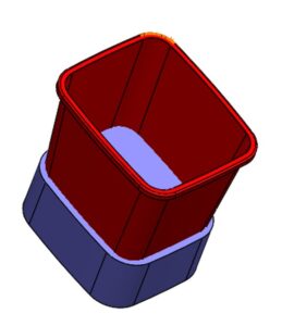
For reference, two models of pot were shared to check and choose the best suitable to fit 8 pots as per the shared sketch.One model (HP5181) was selected for the tray design and it was designed as per the sketch contraption. - Meeting with customer for feedback
Meeting was held for feedback from customer after submission of Concept 1 design.Weight and tray height needed reduction as per the feedback.
Current weight of the tray was 600 grams.
Also, thin and shallow tray design was offered to considered for design improvements. - Concept 2
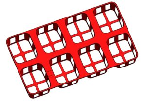
In phase 2 of design, competitive analyses were done from the market available plant trays.
Weight was reduced from 600 to 130 grams by doing all the effective features like thinning and shallowing of the excess area of the tray.A meeting was held for the reviews from customer and concept 2 design was approved by the customer.After final approval, the design needed fine tuning and finally it was prepared for DFM by adding all the features required for injection molding as stated above.
- Design summary
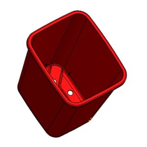
Here shown is the plant pot, based on this model, we need to design the tray of size mentioned for 8 pots.
- Create base rectangle sketch for tray.
- Cutout sections were introduced for drainage and light weighting.

- Contraption done as per the layout defined by the customer.
 4. Add ribs using Rib tool with automatic draft.

5. Applied fillets to all internal corners.

6. Used Shell tool to optimize weight.

7. Thickness Analysis ensures uniform wall distribution.

DFM Validation and Mold Flow Analysis
Mold flow analysis predicts material flow, cooling, and shrinkage. Simulation identifies potential weld lines, air traps, and hotspots.
Cost & Manufacturing Efficiency Analysis
DFM directly influences manufacturing cost. Factors include:
– Tooling cost: Reduced by eliminating undercuts and sharp corners.
– Cycle time: Lowered with uniform walls (average ~30–40s per tray).
– Material usage: Optimized with ribs instead of thick walls.
– Ejection efficiency: Reduced wear prolongs tool life.
Conclusion
This report demonstrates how SolidWorks and DFM principles combine to create a manufacturable, cost-effective, and durable plant tray. Through careful design of wall thickness, ribs, draft angles, fillets, and gating strategy, the tray is optimized for injection molding. Case studies validate the impact of DFM on reducing defects and costs. Future work may include automation of tray nesting and further optimization of cooling channels. DFM is not just a design practice—it is economic advantage in high-volume production.